Download
1 / 18
180 likes | 277 Views
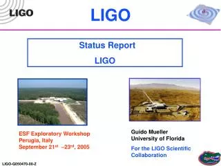
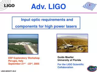
Adv. LIGO. Input optic requirements and components for high power lasers. Guido Mueller University of Florida For the LIGO Scientific Collaboration. ESF Exploratory Workshop Perugia, Italy September 21 st –23 rd , 2005.

E N D
Adv. LIGO Input optic requirements and components for high power lasers Guido Mueller University of Florida For the LIGO Scientific Collaboration ESF Exploratory Workshop Perugia, Italy September 21st –23rd, 2005
Input Optic for Advanced LIGO Requirements for Adv. LIGO Layout Modulators Mode cleaner Isolator Table of Content Documents: LIGO-T020020-00-D IO-Subsystem Design Requirements Document LIGO-T020027-00-D IO-Subsystem Conceptual Design Document LIGO-T010075-00-D Advanced LIGO Systems Design LIGO-T020097-0-D Auxiliary Suspended Optics Displacement …
Advanced LIGO • Changes which affect the input optics: • Detuned Signal-recycling • Higher Laser Power • Increased Arm Finesse: T=0.5% • Decreased Recycling • Cavity Finesse: T=6% 40 kg SILICA Iso. PRM Power Recycling Mirror BS Beam Splitter ITM Input Test Mass ETM End Test Mass SRM Signal Recycling Mirror PD Photodiode
Detuned Signal Recycling Creates asymmetric RF-sidebands All demodulated signals are sensitive to phase between RF-sidebands and carrier (no technical noise suppression) For RF-sensing scheme: Modulation phase stability req.: ISSB (10 Hz) < -92 dBc/Hz ISSB (100 Hz) < -140 dBc/Hz ISSB (1 kHz) < -163 dBc/Hz Compare with Rb Standard: PRS10 (Stanford Research) ISSB (10 Hz) < -130 dBc/Hz ISSB (100 Hz) < -145 dBc/Hz ISSB (1 kHz) < -150 dBc/Hz But that is for a 10MHz signal not 180MHz! Options: 1. Lock to IFO 2. Reduce Frequency 3. DC-Sensing Requirements
Detuned Signal Recycling DC-sensing (now baseline): RF signals are used only for auxiliary d.o.f.s Requirements unclear. Complicated function of locking scheme, cross coupling between channels, noise spectrum, and feedback bandwidth. But will be less difficult than in RF sensing. DC-sensing has additional advantages Lower Shot noise Less sensitive to laser frequency noise Reduced requirements on high-frequency, high-power photo detectors …. Requirements
Higher Laser Power Relative Intensity Noise (RIN): Generates technical RPN in arm cavities Couples to asymmetry in arm cavity build-up Only important for Carrier, sideband power noise does not create RPN! Requirement: 2x10⁻⁹ RIN/rHz @ 10 Hz on carrier intensity! Stabilization will work with main laser beam (carrier + SBs) Any change in the modulation index (SB power) will be undetected in the intensity servo but will change carrier power and generate RIN Generates a requirement for the stability of the modulation index: dG < 10-10/G (f/Hz) 1/rHz (includes safety factor of 10) For G=0.1 dG< 10-8 /rHz @ 10Hz Experimental tests on their way, but this is non-trivial! Requirements
Laser Beam Pointing at PR-mirror: Couples to misaligned mirrors Trade off between pointing and DC alignment Measured in terms of 10-amplitude relative to 00-amplitude: Requirements Optics Express, Vol13(18) pg.7118
Spatial Mode quality: 10-mode ~ misalignment (just discussed) BE-more (20+02 mode) ~ mode mismatch Depends on thermal lensing in main IFO (TCS-system) Content in all other modes should be below < 2% Power issue, no direct noise coupling expected (calculated) Requirements Additional Requirements: See LIGO Documents mentioned on 2nd page
Modulators Mode Cleaner Faraday Isolator Stable Recycling Cavities IO Hardware
LIGO I modulators will not handle the increased laser power (losses and subsequent thermal lensing to high) New materials: KTP, KTA, RTA, RTP have high damage thresholds and high EO-coefficients. RTP has also very low optical and electrical losses. Measurements at 50 W haven’t shown any measurable thermal lens. Long term (16d) measurements at ~100W did not show any degradation. Then laser failed. Requires additional long term, high power testing but looks OK. Parallel vs. complex Modulation: Cross products (SB on SB) generated in serial modulation might need to be reduced: Parallel modulation in Mach-Zehnder Complex modulation using additional AM-modulator Modulators
Modulator • Sources: • RTA-Crystals: • Raicol in Israel • Complete Modulator: • Self made, need probably 3/IFO + spares • Also collaborate with New Focus to build their modulator around our RTA crystals
Serial Modulation: Parallel Modulation Complex Modulation Modulation Schemes Problem: SB on SB modulation Has same frequency than SB-SB beat Frequency Frequency (modulate also at SB-SB frequency with opposite sign)
Requirements: Length Stability < 3.6x10⁻¹⁵ (Hz/f) m/rtHz for (f<1kHz) (RPN?) Mode cleaning Angular Stability: Current Design: Triangular Cavity Flat mirrors at Input and Output near MC waist Curved mirror at acute angle ROC=26.9m (cold), expect 27.9m (hot) L = 33.2m (Roundtrip), FSR = 9 MHz Finesse = 2000 (current design) Was driven by pointing from laser (overestimated pointing) Will probably be reduced (My best guess: 600) Mode Cleaner
High-power Faraday isolators Possible Problems: • Depolarization reduces isolation efficiency • Thermal lensing reduces spatial mode quality Depolarization: • Two novel optical architectures with two Faraday crystals and wave plate (b) or Quartz Rotator (c) • Developed by IAP, Nizhni Novgorod, Russia Thermal Lensing: • Compensated with material with opposite dn/dT, preferably using a crystal, not a glass
l/2 QR Pt Pr H H High Power Faraday Isolator • HP Faraday isolator design uses quartz rotator: • Developed at IAP, Russia • 33dB at 180W laser power • Design with thermal compensation (still with FK51 glass): • No significant lensing up to 90W • Currently under test at LZH
Current Baseline: Recycling Cavities are only marginally stable Essentially flat-flat cavities Will increase scatter of RF-SB and GW-signal into higher order modes Option: Stable Recycling Cavity Move mode matching telescope into Recycling cavity Stabilizes the Recycling cavities and reduces losses into higher order modes Add TCS and we should have very small problems with Thermal Deformations Stable Recycling Cavities
Input Optics for Advanced LIGO: Faraday Isolator, Modulator expected to be able to handle thermal noise w/o degrading the beam quality significantly Mode Cleaner should be fine, no thermal degradation expected Careful with frequency noise driven by technical RPN Mode matching problems related to thermally distorted IFO eigenmode (stable recycling cavities might help) Pointing requirements seem to be within reach Stability of Modulation phase seem to be OK for DC-sensing Likely driven by frequency stabilization servo My main concern: Stability of Modulation index (RIN in carrier field) Unknown spatial mode in main IFO (Greg Harry: TCS) Summary
Input Optics for Advanced LIGO: Faraday Isolator, Modulator expected to be able to handle thermal noise w/o degrading the beam quality significantly Mode Cleaner should be fine, no thermal degradation expected Careful with frequency noise driven by technical RPN Mode matching problems related to thermally distorted IFO eigenmode (stable recycling cavities might help) Pointing requirements seem to be within reach Stability of Modulation phase seem to be OK for DC-sensing Likely driven by frequency stabilization servo My main concern: Stability of Modulation index (RIN in carrier field) Unknown spatial mode in main IFO (Greg Harry: TCS) Summary Warning: This is my opinion and NOT shared by the everybody!