CROSS DRAINAGE WORKS
610 likes | 1.64k Views
CROSS DRAINAGE WORKS. UNIT – 9. LECTURER IN CIVIL ENGG. GP MEHAM. SANDEEP. Cross Drainage Works-Aqueducts. 1. Aqueducts: Classified as: type-I, type-II and type- III depending up on the arrangement of canal passing over the Stream/drain,

CROSS DRAINAGE WORKS
E N D
Presentation Transcript
CROSS DRAINAGE WORKS UNIT –9 LECTURER IN CIVIL ENGG. GP MEHAM SANDEEP
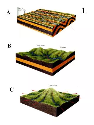
Cross Drainage Works-Aqueducts 1. Aqueducts: Classified as: type-I, type-II and type- III depending up on the arrangement of canal passing over the Stream/drain, • Type-I:Structures come under this type where the canal continuous over the stream with its normal earthen section including the banks and earthen slopes. The HFL of the stream shall be lower than the bottom level of the canal trough. • Type-II: Structures where the canal continues over the stream but the outer banks are replaced by outer walls. • Type-III:The canal banks will be discontinues over the stream and the canal water is carried by a masonry or concrete, RC C Box, Pipe of suitable section. The Service and inspection Tracks may be continuous or discontinues.Generally the canal section is flumed and head loss is accounted for. 2. Viaducts: • Similar to type-III aqueduct except the length of the structure is very large compared to the stream or there is no stream/drain existing in the valleys joining the two sides of the structure. 3. Syphon Aqueduct: • The HFL of the stream/drain will be lower than the under side of (bottom level) the canal trough . If the HFL of the stream is above the canal bed it is called syphoned.
Cross Drainage Works-Aqueducts 4. Under tunnel (barrel/ pipe)/ Syphon Aqueduct: • Stream discharge carried in the barrel if required by depressing stream bed level to make the headway below the canal. Canal section carried over barrel as it is with head walls to replace the outer slopes of canal partially/ fully. The under tunnel flowing full under pressure is called syphon aqueduct. 5. Buttress type under tunnel: • Steam discharge carried in the barrel if required by depressing the stream bed level to make the head way below the canal and canal discharge carried in the flumed trough (Trapezoidal or rectangular). The abutments and piers raised to the bottom of trough in case of Trapezoidal shape. For continuity of inspection path, a bridge and for non inspection path foot bridge will be provided. 6. Super passage: • Stream discharge carried in the trough normally rectangular shape (1 or more bays) with vertical clearance over F.S.L. of canal. For continuity of inspection path bridge and for non inspection path foot bridge will be provided separately. 7. Canal siphon: • Canal discharge carried below the stream by depressing the canal bed to make the headway. For continuity of inspection path a bridge will be provided separately.
CD Works –Level Crossings 8. Level Crossing: • In this type of works the drainage water and canal water are allowed to intermingle with each other . • A Level crossing is provided when large canal and a huge drain approach at the same level. • An Inlet and out let for the canal and an escape for the drainage or vice versa are provided. • Perennial drainage discharge can be used in the canal supplies. 9. Inlets and Out lets: • Provided at exceptional cases.
Cross Drainage Works-Aqueducts Design Criteria : • Hydrology of the drain or stream. • Hydraulic design of • The stream or drain • The hydraulic deign of the canal • Structural Design. • Design of sub structure • Design of super structure
Cross Drainage Works-Aqueducts Basic Data : • Site plan with net levels at 10m intervals and contours and duly marking the flow direction of the canal and the stream. • Hydraulic particulars of the canal • LS of the stream covering 500m on u/s and d/s with levels at 10m to 20m intervals and CSs at centre line and at 10m, 25m, 50m, 100m, 200m, 300m, 400m, and 500m on /s and d/s sides. • Levels on the CS to be 3m, to 5m, in the gorge portion and 10m, intervals on the flanks up to 50m beyond HFL mark on the ground. • Catchment area plan of the seam/drain on the topo sheet for Catchment up to 2.5 Sq..m and the CA to be traversed on ground for Catchment less than 2.5 sq..m. • Computation of Maximum Flood Discharge (MFD) of the stream/drain. and the HFL/ MFL are to be marked on ghe LS & CSs and cross checked with the Observed MFLs (OMFL). • Trial Pit (TP) particulars (Bore logs) taken up to hard strata, for a minimum depth of 2m below ground level or drain bed level or canal bed level for shallow foundations and up o 1.33R below maximum scour level on the centre line of the structure, (and) at least one on either side or as decided as per the filed conditions along the centre line and One each on u/s and d/s side. • Safe bearing capacity of the strata may be obtained and furnished.
Cross Drainage Works-Aqueducts Hydraulic data: • Canal • Width of road way and class of IRC loading. • Head loss provided. • The Stream or drain: • Allowable afflux. • Nature of bed material and value of ‘n’
Cross Drainage Works-Aqueducts I. Hydrology of the drain: • Computation of maximum flood discharge and the MFL II. Hydraulic design: • Water way/Vent way: • Vertical Clearance: • Free Board: • Crust Level of the Road way or a Bridge: • Afflux: • Depth of Scour: • Mean Depth of Scour (d): • Maximum Depth of Scour or Designed Depth of Scour (D or R): • Uplift • Exit gradient. • Loss of Head (Energy Loss): • Joints: III. Structural Design: • Super structure • Sub structure
Aqueducts - Hydrology I.Hydrology of the Drain/Stream: • 1. Compute the designed flood of the stream from catchments area plan using any one of the empirical formulae or by the flood frequency method, SPF, PMF. • 2. Compute the MFL in the stream by step by step method by trial and error and verify with observed MFL. • 3. For drains with discharge > 150 cumecs and canals with discharge > 30 cumecs detailed study is to be conducted in respect of Catchment area and computations of HFD/SPF or PMF.
Aqueducts - Hydrology I. Hydrology of the Drain/Stream: • Formulae for computation of maximum Flood Discharge: _____________________________________________________________ S.No. Type of Canal Catchment Area (CA) in ‘M’ in Sq. Miles ---------------------------------------------------------------------------------------------------------- Up land Areas Deltaic Tracts -------------------------------------------------------------------------------------------------------------------------------------------------------- 1. Main Canal Dickens’s formula, Rye's formula Q = CM 3/4 Q = CM 2/3 C=1400 for CA<1.00 C=1000 C=1200 for CA=1 to 30 Velocity shall not exceed 10 ft/sec C=1060 for CA=30 to 500 -------------------------------------------------------------------------------------------------------------------------------- Q=7000 M1/2 for CA>500 Velocity in the barrel up to 12 to13 ft/sec ------------------------------------------------------------------------------------------------------------------------------- 2. Branch Canal Q=CM 2/3 Q > 500 c/s C=1000 and Velocity<10’/sec same as upland area ------------------------------------------------------------------------------------------------------------- 3. Distributaries Q = CM 2/3 same as upland area Q < 500 c/s C=750 and Velocity< 10”/sec ------------------------------------------------------------------------------------------------------------------------------------------------- Lr. No. CDO/EE-C1/1084/83-3 dated 23.08.1983.
CD Works - Aqueducts • Water way / Vent way and the Lay out: • Design the vent way of the stream/drain limiting the velocities in the drain, Keeping in view the Lacey’s wetted perimeter limiting the fluming ratio to 60% to 80% and velocity<3m/s. • A vent way in Masonry with RCC trough or RCC box with height not less than 1200mm (1500mm preferred) • For smaller discharges RCC Hume pipes diameter no <900mm • Design the tail channel and the approach channel Drain transactions : • Wings and returns are provided both on u/s and d/s side of the stream with splays 2:1 but not flatter than 4:1 on the u/s and 3:1 but not flatter than 5:1 both on d/s side. • Drop wall on the d/s side of the structure may be avoided. • Design/Fix the canal trough limiting the fluming ratio not more than 70% and energy losses not greater than the values provided in HPs and velocity generally not more than 3 to 4m/s. • Transition lengths both on the u/s and d/s side of the canal is fixed. • Canal transitions 2:1 and 3:1 splay but not flatter than 4:1 and 5:1 on u/s and d/s respectively.
CD Works - Aqueducts • Transition walls : Transition walls to be provided at either ends keying 600mm in to the earth banks both for drain and canal. • Compute the TELs of the canal starting from d/s side end of the canal transition up to u/s side transition of the canal (Designed canal section on either side) and verify that the head loss and the velocities are with in the permissible limits. • Finalize the widths of the inspection tracks foot paths on either side if required. • Design the tail channel and the approach channel of the stream. • Compute the TELs in the stream limiting the velocities, and permissible afflux etc. • Draw flow diagrams both for the stream and canal. • Compute and design foundation levels considering scour depths. • Compute and design the barrel and the floors of the stream for uplift pressure. • Check for exit gradient. (cont…)
CD Works - Aqueducts Lay out : • Preferably a straight reach. • The carrier canal and the drain shall be at right angle crossing. • Proper training works for the drain and suitable protection works like turfing, pitching and launching aprons etc., • Expansion joints, Contraction Joints and construction joints.
Aqueducts–Hydraulic Design II. Hydraulic Design: • Vertical Clearance: • It is the vertical distance between the HFL of the stream and the under side of the canal trough including afflux. S. No. Designed flood in Cumecs Minimum Vertical Clearance in mm 1. < 3 450 2 Between 3 and 30 600 3. Between 30 and 300 900 4. Between 300 and 3000 1200 5. 3000 and above 1500
Aqueducts–Hydraulic Design • FreeBoard: • It is the vertical distance between the HFL/FSL to the top of embankment/TBL in case of stream and canal respectively. • Crust Level of the Road way or a Bridge: • The TBL of the canal or the crust level of the road way or the natural ground level which ever is higher. • Afflux: • It should be restricted to the value which should not cause serious bed scours or submergence. • It is the rise in water level on the upstream due to an obstruction to the flow of drain or canal. • It is computed using the Rational formula, Orifice formula or Empirical formula • It is the vertical distance measured from HFL or FSL to the underside of trough, including afflux.
Aqueducts – Hydraulic Design Scour: • Mean Scour Depth: • Mean scour depth is the depth (d) below HFL or FSL in m d = 1.34[q2 /f]1/3 • Where, q = Discharge per meter width with or without concentration of flow in cumecs, f = Layce’s silt factor expressed as f = 1.76 (d m )1/2 • dm = average grain size • Designed Scour Depth (Dor R): • Straight reaches for individual foundations without floor protection In the vicinity of pier 2.00 d Near abutments 1.27 d approaches retained 2.00 d scour all round • For floor protection works, for raft foundations and shallow foundations In straight reaches 1.27 d At moderate bends 1.50 d
Aqueducts – Hydraulic Design At sever bends 1.75 d m At right angle bends 2.00 d Structures and earth work connections: • Uplift: • Uplift under floor of the barrels and under the u/s and d/s side floors caused by the seepage flow from the canal when it is running full and the drain is dry or vise versa may be accounted for the design using the Khosla’s theory and the thickness checked for adequacy. • Cut off walls may be provided on either ends. • For reducing the uplift and exit gradient pucca floor should be provided for in the canal bed in adequate length u/s and d/s side with cut off walls at the ends. • Exit gradient. • The rigid structure and the flexible earth work shall be properly connected and checked for exit gradient (GE). GE = H/d[1/ (Πλ) 1/2]
Aqueducts – Hydraulic Design • Loss of Head (Energy Loss): • The losses are at inlets (h1) and outlets (h2), at bends elbows (h3), losses due to transitions (h4) and losses due to skin friction (h5). The sum of losses (H) shall be sum of all the losses H = h1 + h2 + h3 + h4+h5 • Joints: • Bell Mouth on U/S side: • Cut and ease waters: • Water Stops: • Bearings: • Miscellaneous works:
Aqueducts – Structural Design III. Structural Design: • Design Loads: • Dead Loads • Live Loads • Impact and Dynamic Loads • Water Load • Braking force • Wind Load • Water currents • Centrifugal forces • Buoyancy • Earth pressures • Temperature Forces • Erection Loads. • Seismic Loads. • Water Pressure.
Aqueducts–Structural Design III. Structural Design: • Combination of Loads: • a. Canal empty and drain at low water - normal condition with & without earth quake • b. Canal at FSL and drain at low water - normal condition with & without earth quake • c. Canal empty and drain at HFL - normal condition without earth quake • d. Canal at FSL and drain at HFL - normal condition without earth quake • e. Construction condition: without earth quake • 1. Piers constructed without super structure and drain at HFL • 2. Super structure is constructed on one side of pier and the drain at HFL • Wind load should not be considered simultaneously with earthquake. • The effect of earth quake force in all directions that is Longitudinal (L), Transverse (T), and Vertical (V) shall be taken into with combination T+V or L+V. 5.05.
Aqueducts – Structural Design III. Structural Design: • Super Structure: • Design of RCC Slab under canal and under earth bank or an RCC Box • Inspection Track: To be designed for Single lane IRC class ‘A’ Loading and Foot bridge normally 1.5m wide on non-inspection track. • In case of RCC box, the road way is carried over the box with proper entry and exit on either ends. • Sub Structure. • Design of piers under canal trough and earth bank or inspection track: • Design of abutments under canal trough, and earth banks or inspection track , by adopting TVA procedure, Coulomb’s or Rankin's theory. • Design of abutments under service road / walk way • Design of all retaining walls, such as returns, wing walls, side walls for the drain and canal both on the u/s and d/s side, by adopting TVA procedure Coulomb’s theory or Rankin’s theory.:
CD Works –Structural Design • Design Loads: 1. Dead Loads 2. Live Loads 3. Impact and Dynamic Loads 4. Water Load 5.Braking force 6. Wind Load 7. Water currents 8. Centrifugal forces 9. Buoyancy 10. Earth pressures 11.Temperature Forces 12. Erection Loads. 13. Seismic Loads. 14. Water Pressure. • Combination of Loads: a. Canal empty and drain at low water - normal condition with & without earth quake b. Canal at FSL and drain at low water - normal condition with & without earth quake c. Canal empty and drain at HFL - normal condition without earth quake d. Canal at FSL and drain at HFL - normal condition without earth quake e. Construction condition: without earth quake 1. Piers constructed without super structure and drain at HFL 2. Super structure is constructed on one side of pier and the drain at HFL
CD Works –Structural Design • Design Loads: 1. Dead Loads 2. Live Loads 3. Impact and Dynamic Loads 4. Water Load 5.Braking force 6. Wind Load 7. Water currents 8. Centrifugal forces 9. Buoyancy 10. Earth pressures 11.Temperature Forces 12. Erection Loads. 13. Seismic Loads. 14. Water Pressure. • Combination of Loads: a. Canal empty and drain at low water - normal condition with & without earth quake b. Canal at FSL and drain at low water - normal condition with & without earth quake c. Canal empty and drain at HFL - normal condition without earth quake d. Canal at FSL and drain at HFL - normal condition without earth quake e. Construction condition: without earth quake 1. Piers constructed without super structure and drain at HFL 2. Super structure is constructed on one side of pier and the drain at HFL
CD Works –Canal Syphon • Definition: • Structure, where the drain is taken over the canal such that the canal water runs below the drain either freely or under syphonic action: • When the FSL of the canal is below the under side of the drainage trough and canal water flows freely under gravity, the structure is known as Superpasage. • When the canal FSL is below the under side of the drainage trough, so that the canal flows under syphonic action under the trough, the structure is known as Canal Syphon or a Syphon. • Canal may be flumed for economy, subject to the availability of head loss in the HPs • The drainage trough should not be flumed. • Inspection Track: can not be provided along the canal. • A separate bridge/Causeway will be provided for inspection track.
Cross Drainage Works-Syphon • Hydrology of the drain: • Computation of maximum flood discharge and the MFL • Hydraulic design: • 1. Water way/Vent way: • 2. Vertical Clearance: • 3. Free Board: • 4. Crust Level of the Road way or a Bridge: • 5. Afflux: • 6. Depth of Scour: • Mean Depth of Scour (d): • Maximum Depth of Scour or Designed Depth of Scour (D or R): • 7.Uplift • 8. Exit gradient. • 9. Loss of Head (Energy Loss): • 10. Joints: • Structural Design: • Super structure • Sub structure
CD Works –Canal Syphon • Lay out: • Shape can be circular or rectangular. • RCC barrel, pre cast RCC pipes, or masonry etc., • Syphon barrel: • Horizontal under deep bed portion with slope not steeper than 1 in 3 at entry and 1 in 5 at the exit end. • The invert level at the entry normally be kept at bed level. • The invert level at the exit end be little lower taking into account the loss of head. • Transition walls with splay 3:1 and 4:1 at the entry and exit end. • Stop log groove • Trash Rack • Miscellaneous items/works:
CD Works – Level Crossings • Level Crossing: • Definition: • It is CD work admitting the drainage water in to the canal. • In this type of works the drainage water and canal water are allowed to intermingle with each other . • A Level crossing is provided when large canal and a huge drain approach at the same level. • An Inlet and out let for the canal and an escape for the drainage or vice versa are provided. • Perennial drainage discharge can be used in the canal supplies. • Lay out : • Combination of all or any one of them • Canal inlet regulator • Drainage inlet regulator • Canal outlet regulator • Drainage outlet regulator
Cross Drainage Works- Inlets & Outlets • Inlets and outlets: • Definition: • A canal inlet is constructed when the cross drainage flow is small and its water may be absorbed into canal without causing appreciable rise. • Inlets are provided in exceptional cases only. • When the drain discharge is very negligible and less than 5%, an inlet is provided. • An out let or an escape shall be provided, when the total inlet discharge exceeds more than 15% of the canal discharge. • In drought prone areas or zones of scanty rain fall or the tail end command, the drainage water can be supplemented.
Cross Drainage Works- Escapes • Escapes & Escape Regulators: See under controlled structures • Escapes are safety valves for the canal system, provided to escape surplus water or excess water from the canal. • Though the canals are regulated, excess rise in water level may take place at a point on the canal down stream as a result of entry of storm water, or sudden reduction in demand or closure of out lets down stream, or faulty water regulation may cause breaches, out flanking or dangerous leaks in the canals banks. • Similar situation may happen in the lift irrigation system, when the pumping mains on the down stream fail suddenly. • Hence surplus escapes are provided: • 1 To control the water levels in such situations and avoid damages to the system. • 2. To empty the canal system for repair and maintenance. • 3. As scouring sluices at the head reaches.