Download
1 / 16
180 likes | 394 Views
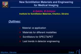
New Scintillation Materials and Engineering for Medical Imaging. A.Gektin, B.Grinyov Institute for Scintillation Materials, Kharkov, Ukraine. Outlines: Material vs application Materials for different modalities Scintillators for SPECT&PET Last trends in detector engineering.

E N D
New Scintillation Materials and Engineering for Medical Imaging A.Gektin, B.Grinyov Institute for Scintillation Materials, Kharkov, Ukraine • Outlines: • Material vs application • Materials for different modalities • Scintillators for SPECT&PET • Last trends in detector engineering
Modality Energies X-ray imaging Mammography 25 kVp, ~18 keV Radiography, chest 150 kVp Fluoroscopy 150 kVp X-ray CT 150 kVp Nuclear medicine Scintigraphy 80 - 140 keV SPECT 60 - 511 keV PET 511 keV transmission emission Radiation in Medical Imaging Two options: Anatomic and/or Functional Image
Columnar CsI:Tl X — Ray screens. Digital Radiography Amorphous silicon Spectral Matching From film to digital screen 50 mkm – spatial resolution
X-ray Computed Tomography Ceramic Scintillators density light yield dec. time afterglow wavel. max. (g/cm3) (phot./MeV) (μs) (% after (nm) 3/100 ms) CdWO4 20,000 7.9 5 < 0.1/ 495 0.02 Bi4Ge3O12 (BGO) 7.1 9,000 0.3 480 > 6 >2/0.3 550 CsI:Tl 4.5 66,000 8 - Gd2O2S:Pr,Ce,F 7.3 35,000 4 < 0.1/< 0.01 510 Gd2O2S:Pr (UFC) 7.3 50,000 3 0.02/0.002 510 Y1.34 Gd0.60 O3:(Eu,Pr)0.06 5.9 44,000 1000 4.9/< 0.01 610 (Hilight) Gd3Ga5O12:Cr,Ce < 0.1/0.01 730 7.1 40,000 140 Lu2O3:Eu,Tb 9.4 30,000 > 1000 > 1/0.3 610
SPECT: current standard practice (basic!) • dual head acquisition • filtered back projection • gated cardiac acquisition • dynamic acquisition (never) • Chang attenuation correction (sometimes) • measured transmission (available at few sites) • iterative reconstruction (available but underutilized) • scatter correction (limited use) • motion correction (available but crude!) • resolution compensation (not usually available) • partial volume correction (what’s this?)
NaI(Tl) gamma cameras history Single head camera 21 century scintimamography cylindrical detector 2000th high spatial resolution curve NaI(Tl) detector coincidence measurement dual head detector 90th SPECT tomography dual head camera Dual head camera 80th single head camera rectangular detector whole body imaging 70th single head camera circular detector Anger invention prototype 1959 www.siemens.de
light output A – slotting B – no slots x Last years SPECT upgrades Coincidence mode detector “Curve Plate” technology Slotted scintillator Cylindrical detector techique g–– quantum From conventional to dedicated and dual mode SPECT systems
Opportunities for development Multi-modality imaging as a precursor for advanced analysis
Matrix + light guide Anger Logics • Different Designs for the Same Application Continuouscrystal Partly pixilated crystal • Dual mode (PET/SPECT) imaging system
Underlying Principle of PET. (Positron Emission Tomography) Collimated 511 keV quanta detected in coincidence Detector ring diameter 0.8-0.9 m
Positron Emission Tomography PET Scintillators 1/μ511 keV light yield (g/cm3) (mm) /PE (%) (photons/MeV) (ns) (nm) Bi4Ge3O12(BGO)7.1 11.6 / 44 9,000 300 480 Lu2SiO5:Ce (LSO) 7.4 12.3 / 34 26,000 40 420 Gd2SiO5:Ce (GSO) 6.7 15 / 26 8,000 60 440 LuxY1-xAlO3:Ce(LuAP) 8.3 11.0 / 32 11,000 18 365 Lu2Si2O7:Ce (LPS) 6.2 14.5 / 29 20,000 30 380 Energy resolution poor
Depth of Interaction LuAP LSO APD array Pulse shape discrimination incorrect Line of Response New PET Developments DOI — Depth of Interaction Special resolution increase
1600 1000 counts 0 600 700 energy [keV] New Scintillators. High Energy Resolution LaCl3:Ce(10%) LaCl3:Ce Time resolution Energy resolution ΔE/E = 3.1% Light yield Decay time Non-proportionality LaCl3:Ce
New Scintillation Materials and Engineering for Medical Imaging Conclusions: • Further improvement of scintillator is possible • Search and development of new scintillators are the base for imaging systems upgrade • Advance scintillation detector engineering is the option for new modality development (animal imaging, scintimammography, dedicated images)