Download
1 / 16
170 likes | 447 Views
Timing + LLRF on RTEMS. Overview rtems 4.7 and EPICS R3.14.8.2 Timing Target=“RTEMS-beatnik” PowerPC mvme5500/6100 hybrid Hardware VME PNET Receiver EVG200 with up to 2K data buffer transfer VME-EVR200 with up to 2K data buffer transfer PMC-EVR200 with up to 2K data buffer transfer

E N D
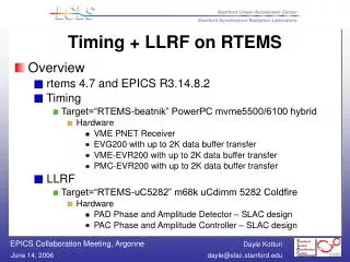
Timing + LLRF on RTEMS • Overview • rtems 4.7 and EPICS R3.14.8.2 • Timing • Target=“RTEMS-beatnik” PowerPC mvme5500/6100 hybrid • Hardware • VME PNET Receiver • EVG200 with up to 2K data buffer transfer • VME-EVR200 with up to 2K data buffer transfer • PMC-EVR200 with up to 2K data buffer transfer • LLRF • Target=“RTEMS-uC5282” m68k uCdimm 5282 Coldfire • Hardware • PAD Phase and Amplitude Detector – SLAC design • PAC Phase and Amplitude Controller – SLAC design
VME PNET Receiver • Driver support • Init: • rc = devRegisterAddress( "pnet", atVMEA24, • vmePnetAddr, PNET_DATA_NUM_BYTES, • (void*)&pLocalBuf); • rc = devConnectInterruptVME(PNET_IRQ_VECTOR, pnetISR, 0); • rc=devEnableInterruptLevelVME(PNET_IRQ_LEVEL) • ISR: • for (ii=0; ii<4; ii++) {/* hdr is in first 4 longs, 0-3, and is ignored. • set initial ii val to 0 if hdr needed • data is in last 4 longs, 4-7, and is of interest */ • pnet_messages[next_message].data[ii] = in_be32(&(pLocalBuf->data[ii])); • } • /* NOW update what current_message is (so that it will be what's accessed */ • current_message = next_message;
LLRF Component Types • Three types of components: PAD, VME and PAC. • 1. PAD – the phase and amplitude detector uses an embedded IOC (uCdimm 5282 Coldfire) • Triggered at 120 Hz, PAD reads 4 channels of accelerator 119 MHz RF(I&Q) from ADCs via TI FIFOs into EPICS waveform record. • FIFOs are 65536 words long, but operationally we use fewer (of order 1k), the size depending on the fill time of the cavity • ADCs are LTC2208 (16 bit, 130 MHz) • Hardware design and CPLD programming by Ron Akre (SLAC) • Last summer, no commercial VME ADC board could match these specifications, so we opted for in-house solution. • Additional advantage: digitizers can be placed next to the low noise RF components (eliminates transmission of low noise analog signals outside the chassis)
LLRF Component Types • 2. VME Feedback Crate uses a mvme6100 • Provides timing trigger to the PAD from EVR200 • Receives averaged I&Q (EPICS ai records) from PAD • Applies phase and amplitude adjustments from global or local feedback • Sends new I&Q (EPICS ao records) to PAC • Provides timing trigger to PAC where corrected waveform is sent out (and NEXT PAD values get read…)
LLRF Component Types • 3. PAC – the phase and amplitude controller uses an embedded IOC (uCdimm 5282 Coldfire) • receives the adjusted I&Q values (EPICS ai records) and computes the waveform to be sent out on next 120 Hz trigger • drives an IQ modulator • used for control of the LLRF to the solid state sub-booster • hardware design and FPGA programming by Jeff Olsen (SLAC)
PAD driver details • Driver support • init: sets up dacq task • ISR: • /* Announce that data is available for read */ • epicsEventSignal(waitForData); • clear the interrupt • Dacq task: • waitStatus = epicsEventWait(waitForData); • Device support • Database records
PAD EDM GUIUse this panel to change the size of and offset to the sample to be averaged.
PAC details • Driver support: update FPGA calculation • Device support • init: waveform record bptr is freed and set to mem-mapped FPGA space • write: waveform is recalculated and result stored in FPGA • Database records • in ops, new adjustment FLNKs to waveform • in cal, new gain or offset FLNKs to waveform
PAC edm control • There are 2 EDM screens • for startup and calibration • at startup the amplitude of the calibration waveform can be modified, as well as number of points in wf • in calibration, the gain and offset of I&Q can be modified • for operation • I&Q can be adjusted (scalar applied to WF[i] *gain before offset is added)