Download
1 / 37
370 likes | 519 Views
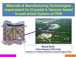
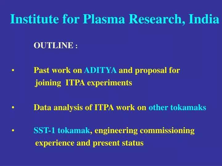
Institute for Plasma Research, India. OUTLINE : Past work on ADITYA and proposal for joining ITPA experiments Data analysis of ITPA work on other tokamaks SST-1 tokamak , engineering commissioning experience and present status. Past work on ADITYA and

E N D
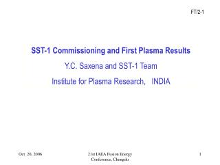
Institute for Plasma Research, India • OUTLINE : • Past work on ADITYA and proposal for • joining ITPA experiments • Data analysis of ITPA work on other tokamaks • SST-1 tokamak, engineering commissioning • experience and present status
Past work on ADITYA and proposal for joining ITPA experiments
ADITYA tokamak (R0=0.75 m, a=0.25 m, BT=0.75-1.5 T, • Ip=75-100 kA, ne20=0.1-0.2, duration= 100-150 ms, RF heating) • has been a rich source of learning experience for us and we have • carried out several experiments related to edge/SOL plasma, • e.g., • Intermittency in turbulence (PRL 1992 ) – first in fusion device • Intermittent particle flux (IAEA 1994) – first in fusion device • Coherent structures giving intermittent flux (PoP 1997) • Wavelets and intermittency (PoP 1996, PoP 1997) • Levy flights (PoP 2003) • Discrete Empirical Modes (PoP 2006) – more later • Fuelling and density limits by gas-puff and MBI (IAEA 2004) • Fluctuation suppression by gas-puff (IAEA 2006) ……………
Er= 1 kV/m B= 0.07 Tesla V= 1.3 km/s B=0.75 Tesla V=16 km/s
During the gas-puff, particle flux is reduced through reduction in density gradient. Reynolds stress gradient also gets suppressed during gas-puff. What happens to the parallel flows in the SOL ? We are presently measuring parallel flows in the SOL with Mach Probe
Based on our experience in studies of edge plasma we propose joining the following ITPA experiments: ? Inter-machine comparison of plasma flows in the edge and SOL plasma and its effect on global confinement (Presently carrying out measurements on ADITYA) DSOL –15 Inter-machine comparison of blob characteristics (Recently purchased fast camera and planning experiments on ADITYA/SST-1) (Inter-machine comparison with dimensionless parameters)
Other ITPA experiment initiated on ADITYA: DIAG-2: Environmental tests on diagnostic First Mirrors (FMs) Two polycrystalline Mo mirrors, one exposed to plasma+GDC and the other only to plasma (in limiter shadow). This will allow us to assess the effect of GDC on the mirrors and help devise ways to protect FMs during wall conditioning process.
ITPA work through other tokamaks We have recently introduced a novel technique based on Empirical Mode Decomposition and Hilbert transform that can detect physically relevant modes from a time-series along with its instantaneous frequency content. [Phys. Plasmas 13, 82507 (2006)] We are applying this technique on two ITPA experiment data : MAST Mirnov coil data - (with Mikhail Gryaznevich) MDC-11 TJ-II fast camera images – (with Carlos Hidalgo)DSOL -15
MDC-11 Fast ions losses and redistribution from localized Alfven Eigenmodes (AEs) Collaborator: Mikhail Gryaznevich (MAST/ JET) Analyzed MAST coil data in discharges with NBI heating (AEs). Our analysis shows two independent AEs as against one that is theoretically expected. The modes are not harmonics as they were believed earlier. Sometimes a single mode is also observed and we need to understand critical conditions required for two modes.
Two independent modes
Two independent modes
A single mode 0.071
Summary of data analysis of ITPA on other tokamaks MDC-11: On MAST data, weneed further analysis to understand the critical conditions required for one or two AEs. Appropriate datasets are being selected and we shall analyze them in coming months. Similar studies on other tokamaks ? DSOL-15: Analysis of TJ-II images require developing or implementing Bi-directional EMD (in space and time). Such developments are already taking place in literature– need some time to learn.
SST-1 tokamak, engineering commissioning experience and present status
SST-1 tokamak • R0 = 1.1 m, a= 0. 2 m • Elongation, = 1.7-2, Triangularity, = 0.4 – 0.7 • BT= 1.5 - 3 T, Ip = 220 kA, ne = 1-21019 m-3 (~0.1 nGW) • Te = 1.5-3 keV, Ti = 1 keV, Pulse duration = 1000 s • Configuration : DN Poloidal divertor • Heating and current drive : • Total power, at any time, limited to 1 MW due to limits of heat extraction at the first wall (Bolted Graphite tiles) • Lower Hybrid (3.7 GHz) : 1.0 MW • ECRH (84 GHz) : 0.2 MW • ICRH (22-91 MHz) : 1.5 MW • Neutral Beam (10-80 keV) : 0.8 MW • Eventually to be upgraded to 5-8 MW total
SC coils: • 16 TF and 11 PF • Resistive coils: • TR (ohmic)= 1+6 • EQ= 2 R (FF,in-vessel) • 2 Z (FF,in-vessel) • 2 R (ex-cryostat)
Overall poloidal cross-sectional view
Basic Diagnostics • Voltage loops Rogowski coils • Diamagnetic coils Faraday sensor • Hall probes Sin, Cos coils • Saddle coils Mirnov Coils • Magnetic coils (Br ,Bz ) Halo current probe • Electrostatic probes Fast ion gauge • Soft and Hard X-ray detectors H monitors • In-vessel inspection system Residual gas analyzer • Thermography
Other Diagnostics • Particle and Heat flux probes • Thomson Scattering • Spectroscopy • (VIS, UV, VUV) • Interferometer • (Microwave, FIR (phase II) ) • ECE Radiation Measurement (Radiometer and Michelson Interferometer) • Bolometer • Soft X-ray Imaging • Passive charge ex diag • Reflectometry • Visible and IR Imaging • He-Beam • Being explored for future: • Charge Exchange (active) • Motional Stark Effect • Polarimetry • Laser Induced Fluorescence • Phase contrast imaging
Comparison of basic plasma parameters with global tokamak data-base. Overlapped yellow circles represent SST-1 parameters. Source: ITER 1D Modeling Working Group, Nuclear Fusion 40 (2000) p.1967 Machine parameters- comparison with global DB Box: 25-75% Bars:10-90% • A=R/a=5.5 • = 1.9 • A =10.5
Dimensionless parameters- comparison with global DB Comparison of expected dimensionless parameters with global tokamak data-base. Yellow circles represent SST-1 parameters. Source: ITER 1D Modeling Working Group, Nuclear Fusion 40 (2000) p.1967
p 0.85 High heat flux on divertor plates and high PF currents High heat flux on passive stabilizer and more backflow 1.4 1.7 li 1.9 Vertical control limit Operational envelope of SST-1 in - li - p space Bounding equilibria Reference equilibria 0.75
Flux surfaces for extreme cases = 1.7, li = 0.75 case, high heat flux on the divertor plate = 1.9, li = 1.4 case, high heat flux on the passive stabilizer Divertor plate Passive stabilizer (R is in mm)
Vision of operational phases Ohmic Phase-I Phase-II Upgrade Phase-III Remove In-vessel comp Circular 1.5 T Add more power Add FW, divertor Add more diagnostics Scaling Expts. AT-modes limiter case 1.5 T, 3 T Short pulse 3 T Long pulse Add new in-vessel comp q=3 91 kA @1.5 T
Experience of engineering commissioning and Present status
Machine assembly completed and first attempt to coil cooling July 2005 Vacuum: in the vessel: 810-7 mbar without baking, in the cryostat: 10-5 mbar Isolators in the LN2 circuit for dielectric break Cool down up to 80 K – cryostat vacuum maintained. --Vacuum failure in cryostat observed at 63 K (SC Magnet) --Higher temperature in some thermal shields (100-180 K). Further cool down stopped. Cryostat ports opened for investigation: --Leak tests showed cracks in some Isolators due to insufficient flexibility.
Preparation for second cool down and power test • Leaks in the cryostat: • Isolators connected with bellows to add flexibility. • Some nitrogen distribution lines were realigned to minimize pressure drop and stress and for better • temperature distribution. • Leaks in some accessible weld joints were repaired. • Power supplies: • Power supplies (TF and PF) received and TF power supply commissioned. • Current leads developed in-house and tested. • Current leads installed for TF coils
Second cool down and power test • June-October, 2006 • Better temperature distribution (100-140K) on thermal shields. • TF magnets reached 4.5 K at the inlet (6K – 8K at the outlet ) • and became super-conducting. • The cryostat vacuum maintained at < 10-4 mbar by operating • the cryogenic lines at less than their normal operating • pressures (1.2 bar instead of 4 bar/liquid phase) • Attempt to raise pressure in the cryogenic line showed leak • (increase in cryostat pressure) • Power test carried out at 4.5 K (1.2 bar) and current quench • observed at ~1 kA
Either one or two coils (TF-10 & 16) showed quench at about 1 kA
Summary of SST-1 status • Successful cool down at lower pressure-- plant capability OK • TF Power Supply tested on current leads (up to 9 kA)-- OK • Current quench at 1 kA -- quench detection circuit OK • OH circuit charged to measure loop voltage --OK • Following the power test and warm up, cryostat ports were opened to identify the problem areas: • … Leaks in the nitrogen circuit, mostly at the isolator joints. • … Leaks in some magnet circuit at termination joints. • As the repair of the helium circuit needs better access, it was decided to cut open the cryostat. • Various options are being evaluated to repair these leaks • (termination joints and isolators).
Concluding remarks: • Repair of SST-1 nitrogen and helium (magnet) • circuits will take some time. • We can carry out ITPA experiments on ADITYA • until SST-1 is put back in operation. • We can participate in ITPA through other tokamaks • (Experiment + Analysis) including remote • participation.