Download
1 / 12
120 likes | 264 Views
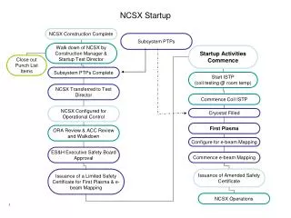
presented for the NCSX Plasma Boundary Group by Peter Mioduszewski ORNL NCSX PAC-7 Meeting July 13-14, 2004. Preparation for Plasma Boundary Research on NCSX. VI. Long-pulse pumped divertor operation: 6 MW divertor pumping 6 MW; several secs 20 Pa m 3 /s exhaust

E N D
presented for the NCSX Plasma Boundary Group by Peter Mioduszewski ORNL NCSX PAC-7 Meeting July 13-14, 2004 Preparation for Plasma Boundary Research on NCSX
VI • Long-pulse pumped • divertor operation: • 6 MW • divertor pumping • 6 MW; several secs • 20 Pa m3/s exhaust • active density control Mission of the Plasma Boundary Program 1. Develop power- and particle exhaust methods compatible with high beta, high confinement operation of NCSX 2. Generate the knowledge base for plasma boundary operation in compact stellarators Evolution of the boundary program: IV III V • Initial Experiments: • 1.5 MW NBI, • partial PFCs • plasma-wall contact • boundary structure • Auxiliary Heating: • 3 MW NBI, • PFC liner • 350ºC bake • edge parameters • power/particle • control • Confinement and • High Beta: • 6 MW, • divertor • power handling • neutrals control • impurity control FY 2008 - 2010 > FY 2010
Status and Preparation of Boundary Modeling Magnetic field topology: 1. VMEC-MFBE*-Gourdon codes (A. Grossman, A. Koniges) 2. PIES-Drevlac-Integrator (T. Kaiser) --> generated Poincaré plots of edge fields and footprints on wall status: both approaches work and are presently being benchmarked against each other needs: foot prints on wall panels and peaking factors of power fluxes Neutrals: we have carried out investigations of neutrals penetration in the “bean” cross-section (for PVR); DEGAS 2-D axisymm.; 3-D for HSX Fast particles: have separatrix exits;need to couple with a field-line code for wall intercepts *E. Strumberger
Status and Preparation of Boundary Modeling cont’d 3-D plasma boundary codes: 1.Started collaboration (LLNL) with Greifswald group on the development of the BoRiS code (no funding at this time) 2. The EMC3-EIRENE code (Feng, Sardei) solves self-consistently plasma, neutrals, and impurity behaviour. It has correctly predicted major parameters of W7-AS, it can treat 3-D structures, islands, stochastic areas. It has been tested on W7-AS, W7-X, LHD, and TEXTOR DED. Bottom line: F. Sardei says it is fully parallelized and it works. Wendelstein group will be happy to train a post-doc… We need to get on board as soon as we have the resources (no later than mid ‘05) !
Boundary Diagnostics Preparation The most likely location for a divertor has excellent diagnostics access. adequate set of initial diagnostics has been identified; views are being defined
Investigation of Plasma-Wall Contact (Phase III) 1.5 MW, Partial PFC GDC Preparatory work: modeling of intercepts with first wall and peaking factors of power fluxes Interaction locations: 1. divertor: helical ridges 2. NBI-wall shine-through 3. fast particle intercepts Diagnostics: fast visible camera visible spectrometer visible filterscopes compact IR camera movable Langmuir probe fast pressure gauges In conjunction with modeling these measurements will provide the input for the divertor design.
poloidal outer midplane Plasma-Wall Contact Modeling : Foot-Prints Used For Divertor and Baffle Design A. Koniges toroidal
Structure of the Plasma Boundary: NCSX vs.W7-AS So far, we are learning from theW7-AS and W7-Xexperience, focused on the island divertor concept: • the divertor intercepts islands, formed by field-lines withvery small pitch angles (10-3) which scale with 1/Lc,leading to very specific effects: • cross-field transport may dominate (control coils) • 2-point divertor model does not apply • observed momentum loss along the field line of factors 4 - 5, in contrast to the usual factor of 2 (detachment!) • ndownstream ≤ nupstream • In NCSXthe field-lines wind around the main plasma. The pitch angles (and divertor config.) are more tokamak-like (0.1). • Long connection lengths are favorable for achieving parallel temperature gradients only with sufficiently large pitch angle.
Structure of the Plasma Boundary cont’d W7-AS NCSX connection lengths are similar field-lines wind around main plasma pitch angle is large (10-1) island field-line pitch angle is very small (10-3) (getting smaller with increasing connection length) divertor plates
Auxiliary Heating Experiments (Phase IV) 3 MW NBI PFC liner 350 ºC baking • Along with 3 MW of NBI, there will be new capabilities for • particle and impurity control: • graphite PFC liner, • baking at 350ºC, • wall coatings • During this phase we will investigate: • more details of the plasma-wall contact areas • power fluxes and wall temperatures • temperatures and densities of the boundary plasma • neutral pressure and particle fluxes during the discharge • the control of neutrals with wall coatings • impurity sources as a function of wall conditions • energetic particles interactions with wall locations • predictive and interpretive modeling Diagnostics: fast visible camera visible spectrometer visible filterscopes compact IR camera movable Langmuir probe fast pressure gauges fast ion loss probe
Summary • Preparations for the plasma boundary program are underway. • Highest priority so far has been modeling of the magnetic boundary topology and defining the boundary diagnostics set. • The most important tasks for FY 2005 are: • develop and finalize the diagnostics views • continued modeling of the magnetic topology (benchmarking) • calculation of foot prints and peaking factors on the wall • conceptual design of the partial PFCs • Other priority tasks are: • plasma and neutrals modeling (EMC3-EIRENE) • energetic particle modeling (wall intercepts)