Download
1 / 66
660 likes | 808 Views
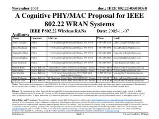
“What I did in my summer internship”. System Design Issues in building a Cognitive Radio Network: IEEE 802.22. Detection of DTV signals at very low SNR using PN sequences. Joint work with Steve Shellhammer (Qualcomm) & Rahul Tandra (U.C. Berkeley).

E N D
“What I did in my summer internship” System Design Issues in building a Cognitive Radio Network: IEEE 802.22 Detection of DTV signals at very low SNR using PN sequences Joint work with Steve Shellhammer (Qualcomm) & Rahul Tandra (U.C. Berkeley)
A brief history of Cognitive Radio and IEEE 802.22 • Apparent scarcity of spectrum • Spectrum use model flawed – allocated but not utilized • J. Mitola coins ‘cognitive radio’ -Ph.D. thesis (May 2000) • FFC issues NPRM for TV bands (May 2004) • 802.22 is born (Sept 2004) • How to protect the ‘incumbent’ ? • May 2006: v0.1 of the 802.22 Draft is shipped • Sept. 2006: FCC Docket: Retail by Feb 2009. • Sensing specs. still not met, broadcasters dissatisfied • Unlicensed economic model still attractive • 3G auction: $17 Bn , $34 Bn , $46 Bn
802.22 deployment scenario 802.22: Fixed wireless broadband access network operating in TV bands (Channel 2 -51) Cellular system, central BS, CPEs (Consumer Premise Equipment) Targeted at but not limited to rural deployment Strict requirements on protections of existing licensed services
Why do we need to detect at such low SNR? Shadow faded CPE
Why do we need to detect at such low SNR? Shadow faded CPE INTERFERENCE
‘Hidden incumbent’ problem • An in-band Incumbent appears at a location where BS cannot sense it but CPE can. • CPE wishes to inform BS about incumbent but may loose sync to BS due to interference from incumbent • BS continues to transmit on the channel occupied by incumbent, causing interference to it.
Sharing licensed spectrum Horizontal sharing Vertical sharing
Horizontal spectrum sharing • An unlicensed user must adhere to FCC guidelines for protection of incumbents. • But other unlicensed systems on the TV bands do not enjoy the same protection. • This means a Cognitive Radio must not only detect, but also classify signals. • Simple narrowband power detection [Tandra & Sahai] does not achieve this objective
Part IIDetection of DTV signals at very low SNR using PN sequences
Outline of Part II • The ATSC standard and PN sequences • Optimal & approximate detectors • Problem with detector a proposed detector • Our detection algorithms • Effects of multipath fading on PN correlation • Fundamental limits in PN seq. detection • Sensitivity to pilot estimate • A comparison of PN and pilot detection • Pilot spectral line detection
ATSC DTV numerology • Symbol rate: 10.76 Msymbols/sec • Data Segment SYNC: A ‘1001’ pattern at the beginning of each segment • Data Field SYNC: An entire segment containing PN sequences: PN511 + PN63 + PN63 + PN63
ATSC framing structure A single VSB Data Segment The Data Field SYNC
Typical ATSC DTV spectrum Pilot tone VSB spectrum at IF 6 Mhz = 1 DTV channel f_IF = 5.38 Mhz Nyquist Rolloff = 0.1152
Simulation Methodology Pull out reqd. # of samples Signal at desired SNR Detection algorithm + X DTV signal captures (50 DTV signals captured at high SNR, provided to us by MSTV Corp.) Scale Threshold calibration Gaussian Noise Multipath fading, noise Test locations in NY, Washington
The optimal PN seq. detector • Assumption: exactly 1 PN sequence present • Generalized Likelihood Ratio Test (GLRT) in favor of H1 iff: • is the MLE given by: • GLRT is:
Approximate detector • Neglect the signal in alternate hypothesis (low SNR) • is the MLE given by • GLRT is: • Threshold can be found easily by using: simply correlate and compare max value with g
A detector proposed by France Telecom • Correlate the received signal, r(n), with the known PN sequence • Use a simple low pass filter to estimate the mean and the variance of the correlator output • An ATSC DTV is declared detected when (d and c are constants set by the BS)
The Problem with this Detector • The estimate of the mean approach zero even for noise only input • This implies that the test statistic can approach zero even for a noise only input signal • This results in false alarms. The detector threshold ‘c’ cannot be calibrated for a given false alarm probability pFA.
Test statistic with noise-only input Correlator output Detector output Output of the correlator when only filtered receiver noise is fed as input. Ratio shows false peaks because mean goes very close to zero.
Detector operation with DTV signal + Noise (SNR = 0 dB) Correlator output Detector output Output of the correlator over duration of 1 ATSC field when DTV signal + noise is fed as input. The peak indicated the position of the PN sequence. Ratio again shows false peaks because mean goes very close to zero
A simple ‘fix’ • Take absolute value of the correlator output before feeding as input to the detector. • Mean cannot go arbitrarily close to zero • The ratio is random for noise input.
Modified Detector with noise input Correlator output Detector output Absolute value of the correlator output when only filtered receiver noise is fed as input. Ratio is random
Modified detector with DTV Signal + Noise (SNR = 0 dB) Correlator output Detector output Absolute value of correlator output over duration of 1 ATSC field when DTV signal + noise is fed as input. The peak indicated the position of the PN sequence. Ratio shows peak at location of PN sequence
A simple test statistic • Correlate received signal with the following sequence: [PN511 + PN63 + 63 zeros + PN63] • Find the tallest peak in the correlator output • Compare its magnitude with threshold
The effect of multipath Phase reversal 48.4 ms
The effect of multipath 6ms ~ 2km dominant echo Multiple peaks
The effect of multipath 6ms ~ 2km dominant echo Multiple peaks Can we utilize multipath in a positive way ? (Lessons from CDMA ?)
Fundamental limits in PN detection • Using a larger received signal for detection does not always improve performance. multipath fading noise enhancement Multipath, jitter and small variations in clock frequency cause timing offsets resulting in misaligned peaks by +/-1,2 samples
Using the Data Segment SYNC • The DATA Segment SNYC is a 1001 pattern • Very non unique but much more frequent (every 77.3 ms=1 seg.) • Present in noise and data quite often, but can we use its periodicity? • A long sequence of the following form can be used for correlation: [1001 (828 zeros) 1001 (828 zeros) … N times ]
The issue of Multiple antennas Power detection PN sequence detection • Power detector is affected by shadowing • Therefore multiple sensors located in INDEPENDENT shadow fades would help • Existence of such independent CPEs not guaranteed (incumbents not happy with the idea) • Multiple antenna on a single CPE do not help (same shadow fade) • The height and polarity of a PN correlation peak depends on the instantaneous fade. • Two or more independent fades would provide different correlation peaks. • If multiple antennas can provide statistically independent fading, they can help. • A simple system would be to run 2 parallel PN detectors and OR their decisions. i.e. Miss detection = (Miss detection 1) AND (Miss detection 2)
Multiple antennas • Running 2 parallel detectors • Assumption: Fading processes at two antennas are statistically independent • We use fields from widely time-separated part of a DTV signal capture to satisfy independent fade assumption • At 600 Mhz, l/2 = 25 cm. A practical antenna array can be built.
The effect of pilot estimation error • The pilot frequency is used in downconverting a passband signal to recover the baseband transmit signal. • How sensitive is PN detection to the estimate of the pilot frequency? • We attempt to measure the effect of pilot estimation error on a PN correlation peak
The effect of pilot estimation error • At low enough SNR even 0.2% error in pilot frequency estimate can be disastrous for PN correlation • Pilot estimation needs to be accurate • Why not use the pilot line as a means for DTV signal detection?
Part IIISpectral line detection of a DTV pilot[Extension of ‘Narrowband pilot energy detection’ done by Rahul Tandra]
Performance of pilot spectral line detection strong pilot • Signal shows a strong pilot • Detector performance is very good even at -25 dB ! Pilot energy detection [Tandra]
Performance of pilot spectral line detection Moderate pilot • Signal shows a moderately strong pilot • Detector begins to fail at -21dB
Performance of pilot spectral line detection Very weak pilot • Pilot is almost completely absent from signal • Detector begins to fail at -16 dB
Doubling the listening time Very weak Pilot
Doubling the listening time Moderate Pilot
Noise Uncertainty • For signals with weak pilots, uncertainty in the noise power estimate can drastically change performance. • We assume D = +/- 1 dB. • How does performance change?