Download

1 / 9
100 likes | 282 Views
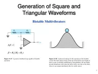
Generation of Square and Triangular Waveforms. Bistable Multivibrators. Figure 13.17 A positive-feedback loop capable of bistable operation.

E N D
Generation of Square and Triangular Waveforms Bistable Multivibrators Figure 13.17 A positive-feedback loop capable of bistable operation. Figure 13.18 A physical analogy for the operation of the bistable circuit. The ball cannot remain at the top of the hill for any length of time (a state of unstable equilibrium or metastability); the inevitably present disturbance will cause the ball to fall to one side or the other, where it can remain indefinitely (the two stable states).
Figure 13.19 (a) The bistable circuit of Fig. 13.17 with the negative input terminal of the op amp disconnected from ground and connected to an input signal vI. (b) The transfer characteristic of the circuit in (a) for increasing vI. (c) The transfer characteristic for decreasing vI. (d) The complete transfer characteristics.
Figure 13.20 (a) A bistable circuit derived from the positive-feedback loop of Fig. 13.17 by applying vI through R1. (b) The transfer characteristic of the circuit in (a) is noninverting. (Compare it to the inverting characteristic in Fig. 13.19d.)
Application of the Bistable Circuit as a Comparator Figure 13.21 (a) Block diagram representation and transfer characteristic for a comparator having a reference, or threshold, voltage VR. (b) Comparator characteristic with hysteresis.
Figure 13.22 Illustrating the use of hysteresis in the comparator characteristics as a means of rejecting interference.
Astable Multivibrators Figure 13.24 (a) Connecting a bistable multivibrator with inverting transfer characteristics in a feedback loop with an RC circuit results in a square-wave generator.
Figure 13.24 (Continued) (b) The circuit obtained when the bistable multivibrator is implemented with the circuit of Fig. 13.19(a). (c) Waveforms at various nodes of the circuit in (b). This circuit is called an astable multivibrator.
Generation of Triangular Waveforms integrator Figure 13.25 A general scheme for generating triangular and square waveforms.
Monostable Multivibrators Figure 13.26 (a) An op-amp monostable circuit. (b) Signal waveforms in the circuit of (a).