Download

1 / 27
270 likes | 387 Views
Status of US ITER Neutronics Activities. Outline Examples of US activities during EDA US ITER neutronics activities in the past year Possible future US contribution to ITER neutronics activities. US Neutronics Computation Capabilities.

E N D
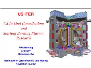
Status of US ITER Neutronics Activities • Outline • Examples of US activities during EDA • US ITER neutronics activities in the past year • Possible future US contribution to ITER neutronics activities
US Neutronics Computation Capabilities • The US has been developing state-of-the-art computational tools and data bases for nuclear analyses • Most recent versions of codes and data will be used in ITER nuclear analysis: • Transport codes: MCNP5 (Monte Carlo), DANTSYS3.0 (ONEDANT, TWODANT, THREEDANT), DOORS3.2 (ANISN, DORT, TORT) • Activation Codes: ALARA, DKR-Pulsar, REAC • Data Processing Codes: NJOY99.0, TNANSX2.15, AMPX-77 • Nuclear Data: ENDF/B-VI, FENDL-2 • Sensitivity/Uncertainty analyses: FORSS, UNCER
U.S. has been Active Participant in ITER Nuclear Analysis During CDA and EDA Examples of US Contribution: • Nuclear assessment of breeding blanket options and magnet shield optimization during CDA • Contributed to development of complete integrated MCNP ITER (EDA) model that includes details of shielding blanket modules, divertor cassettes, VV with ports, TF coils, PF coils, CS coils • Modified MCNP allowing it to sample from actual pointwise neutron source distribution in ITER plasma • Calculated poloidal neutron wall loading distribution at FW and divertor cassette plasma facing surface
3-D Nuclear Analysis for Divertor Cassette • Determined nuclear heating (W/cm3) profiles in divertor cassette • Calculated radiation damage in cassette components • Evaluated adequacy of VV and TF coil shielding by calculating hot spot damage, gas production and insulator dose • Performed 3-D divertor cassette pulsed activation calculations to determine radioactive inventory, decay heat, and radwaste level • Assessed streaming effects
Neutronics Assessment of Divertor Diagnostics Cassettes • Nuclear parameters in waveguides • Streaming through viewing slots • Nuclear parameters in mirror assemblies
2-D R-q Modeling of Two Test Modules Placed in Test Port Distance from plasma center Earlier Work -1996 Two Test modules of the EU Li4SiO4 helium –cooled design are placed in the test model Edge-on Arrangement A lattice consists of FS layer (0.8 cm), Be bed layer (4.5 cm) and SB bed layer (1.1 cm) Buffer zone between modules (10 cm) Upper module has 75% Li-6 (19 lattices), lower module 25% Li-6 (16 lattices) Lower attenuation (higher flux) behind beryllium layers Cos q
Dose Rate (mS/h) in ITER Building During Operation and After Shut Down 2-D Model of ITER Machine Coupled 2-D and 3-D Calculations using Deterministic method (DORT and TORT codes) for neutron and gamma flux calculations and DKR-Pulsar code for dose calculations One Week after Shutdown 2-D Model of ITER Building Tritium Building 3-D modeling
Verification of ITER Shielding Capability with Various Codes and Nuclear Data Participants in this Task: US/JAERI: for thick shield experiments EU/RF: for thin shield experiments R-Z model of SS316/Water assembly Data Verified: Various reaction rates, neutron and gamma spectra, heating rates R-Z Model of the simulated Super conducting magnet in SS316/Water Assembly SS=Shelf-shielded data- SS316/water assembly
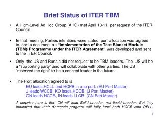
US Nuclear Support for ITER Restarted Following US Rejoining ITER in 2003 Major effort has been in support of ITER TBM program • A study was initiated to select two blanket options for US ITER-TBM in light of new R&D results • Initial conclusion of US community is to select two blanket concepts • Helium-cooled solid breeder concept with ferritic steel structure • Dual-Coolant liquid breeder blanket concepts with ultimate potential for self-cooling • a helium-cooled ferritic structure with self-cooled LiPb breeder zone that uses SiC insert as MHD and thermal insulator • a helium-cooled ferritic structure with low melting-point molten salt
DEMO Blanket Testing in ITER Detailed design of realistic DEMO Blanket DEMO relevant TBM designed TBM inserted for testing in ITER port ITER Blanket DEMO
SW/FW He Inlet/Outlet Manifold Grid Plates First Wall Back Plate He Inlet Pipe LL Flow Outlet Distribution Baffle He Outlet Pipe He Flow Inlet Distribution Baffle Assessment of Dual Coolant Liquid Breeder Blankets in Support of ITER TBM DC-Molten Salt DC-PbLi
Front Flibe Zone, Flow Direction Poloidal Up Be zone Perforated plates FW Coolant channels He ManifoldSeparator plate, Back FLiBe Zone, Flow Direction Poloidal Down 3-D Calculation for DC MS Cross section in OB blanket at mid-plane • Total TBR is1.07 (0.85 OB, 0.22 IB). This is conservative estimate (no breeding in double null divertor covering 12%) • 3-D modeling and heterogeneity effects resulted in ~6% lower TBR compared to estimate based on 1-D calculations • Peaking factor of ~3 in damage behind He manifold
Preliminary Neutronics for DC PbLi Blanket • Nuclear energy multiplication is 1.136 • Peak nuclear heating values in OB blanket • o FS 36 W/cm3 • o LL 33 W/cm3 • o SiC 29 W/cm3 • Blanket thickness • OB 75 cm (three PbLi channels) • IB 52.5 cm (two PbLi channels) • Local TBR is 1.328 • OB contribution 0.995 • IB contribution 0.333 • If neutron coverage for double null divertor is 12% overall TBR will be ~1.17 excluding breeding in divertor region. To be confirmed by 3-D neutronics • Shield is lifetime component • Manifold and VV are reweldable • Magnet well shielded
Two Types of Helium-Cooled SB PB modules under consideration for Testing in ITER Type 1: Parallel Breeder and Multiplier: Type 2: Edge-On configuration Local TBR: 1.2 In Demo Configuration- 1-D NWL 0.78 MW/m2 75% Li-6 enrichment Packing factor for Be and Li4SiO4 Pebble beds 60% Local TBR: 1.04 In Demo Configuration- 1-D
Neutronics module under evaluation to ensure that design goals are met Goals • Determine geometrical size requirements such that high spatial resolution for any specific measurement can be achieved in scaled modules • Allow for complexity, to maximize data for code validation • Proposed scheme is to evaluate two design configurations simultaneously; however 2-D (3-D) neutronics analysis must be performed to ensure that design goals are met. • Demo Act-alike versus ITER-optimized designs • Structural fraction: • ~ 23% Demo Vs. ~21% ITER • Total number of breeder layers/layer thickness: • 10 layers/13.5 cm Vs. 8 layers/14.9 cm • Beryllium layer thickness: • 19.1 cm vs. 17.9 cm
2-D R-theta Model developed for DORT discrete ordinates calculations to analyze the nuclear performance of the US two sub-modules with actual surroundings Close-up radial details Details of Theta variation at the Port Top View
Nuclear Heating in FW of The Two U.S. Test Blanket Configurations in the Toroidal Direction Toroidal Profile of Tritium Production Rate in each Breeder Layer of the Two Test Blanket Configurations • Profiles are nearly flat over a reasonable distance in the toroidal direction where measurements can be performed with no concern for error due to uncertainty in location definition • Steepness in profiles near the edges is due to presence of Be layer and reflection from structure in the vertical coolant panels
US will Contribute to ITER Nuclear Analysis • US Contribution to ITER Nuclear Analysis will be in the following areas: • Nuclear analysis for ITER TBM • Nuclear support for basic ITER Machine • Development of CAD/MCNP interface • Level of effort will depend on availability of funding
Nuclear Analysis for TBM • TBM designs will be developed andmodeled for 3-D neutronics calculations with all design details • The TBM 3-D model will be integrated in the complete basic ITER machine 3-D model • Perform 3-D neutronics calculations using the integrated model • Neutronics calculations will provide important nuclear environment parameters (e.g., radiation damage, tritium production, transmutations, radioactivity, decay heat, and nuclear heating profiles in the TBM) that help in analyzing TBM testing results
Cryo pump duct Cryostat IVV channel Cryo pump Detailed Nuclear Analysis is Needed for ITER Basic Machine During Design and Construction Phases • ITER is still undergoing major design changes • As ITER moves toward construction, more accurate nuclear analysis becomes essential part of final design process • Experience shows that neutronics and radiation environment assessments continue through final design and construction phases of nuclear facilities • Examples include • TFTR and JET • Spallation Neutron Source
Nuclear Analysis for ITER Basic Machine • This will include computation of radiation field, radiation shielding, nuclear heating, materials radiation damage, and absorbed dose to insulators and other sensitive components • Three-dimensional neutronics calculations will be performed using MCNP5 and FENDL/MC-2.0 • Activation analysis will be planned to support safety assessment of the site-specific issues as needed. This includes calculating radioactive inventory,decay heat, and maintenance dose • Activation calculations will be performed using the state-of-the-art ALARA pulsed activation code along with the FENDL/A-2.0 activation data • Radiation leakage through holes and other penetrations must be fully assessed to establish activation levels for personnel access
Neutronics Support for Module 18 of FW/Shield (Baffle) • We will provide neutronics support for design and construction of module 18 • 3-D neutronics calculations using the full ITER model will be performed to determine nuclear heating and radiation damage in components of module 18 Module 18
Nuclear Analysis for Diagnostics Ports • Many diagnostics systems will be employed in ITER at upper, equatorial and lower ports • Neutron and gamma fluxes affect diagnostics performance • Determination of radiation environment is essential for estimating shielding requirements for diagnostic components such as insulated cables, windows, fiberoptics and transducers, as well as detectors and their associated electronics • Radiation leakage through penetrations in these diagnostic systems must be fully assessed to establish activation levels in and near diagnostic equipment where frequent access will be necessary • We will coordinate with diagnostics group to provide needed nuclear support
Neutronics Support for Heating and CD Systems • Will support Ion Cyclotron and Electron Cyclotron heating and current drive systems • These systems have sensitive components (antennas, RF sources, gyrotrons, insulators, and transmission lines) and neutronics support will be essential to address radiation damage and streaming issues We will coordinate with plasma heating group to provide neutronics support as needed ITER ion cyclotron system block diagram
In FY04, we provided neutronics support to US effort on ITER CS • Concern was that helium embrittlement could be a problem for proposed JK2LB steel conduits (employed in place of Incoloy 908) with deliberate boron additives at some grain boundaries • Concluded that helium embrittlement of JK2LB will not be a problem, even with a 50% B concentration at the grain boundaries • Will continue providing neutronics support as needed to ITER CS Neutronics Support for ITER Central Solenoid
MCNP CGM MCNP Native Geometry θT ACIS Pro/E Voxels OB IB θT OB IB CAD-Based MCNP Fusion TechnologyInstitute Parallel Computing Sciences Department • Use Sandia’s CGM interface to evaluate CAD directly from MCNP • CGM provides common interface to multiple CAD engines, including voxel-based models • Benefits: • Dramatically reduce turnaround time from CAD-based design changes • Identified as key element of ITER Neutronics analysis strategy • No translation to MCNP geometry commands • Removes limitation on surface types • Robustness improved by using same engine for CAD and MCNP • Provides 3rd alternative for CAD-MCNP link • Can handle 3D models not supported in MCNP • Status: prototype using direct CAD query from MCNP • Issues/plans: • (Lack of) speed: 10-30x slower than unmodified MCNP • Key research issue: ray-tracing accelerations (lots of acceleration techniques possible) • Support for parallel execution (CGM already works in parallel) • Goal: speed comparable to MCNP, but using direct CAD evaluation ARIES-CS Plasma