Progress Update on Spectrometer Solenoids and Coupling Coils Development
290 likes | 424 Views
This report outlines the current progress of the Spectrometer Solenoids (SS#1 & SS#2) and Coupling Coils for the MuCool project. Key achievements include the successful training of SS#2 to full flip and solenoid mode currents, and improvements in the control systems to enhance safety and reliability. Major upcoming tasks include 3D magnetic mapping of SS#2 and assembly of the second unit. Risks have been identified and mitigation strategies implemented to ensure continued progress and operational readiness.

Progress Update on Spectrometer Solenoids and Coupling Coils Development
E N D
Presentation Transcript
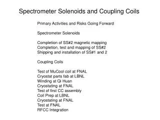
Spectrometer Solenoids and Coupling Coils Primary Activities and Risks Going Forward Spectrometer Solenoids Completion of SS#2 magnetic mapping Completion, test and mapping of SS#2 Shipping and installation of SS#1 and 2 Coupling Coils Test of MuCool coil at FNAL Cryostat parts fab at LBNL Winding at Qi Huan Cryostating at FNAL Test of first CC assembly Coil Prep at LBNL Cryostating at FNAL Test at FNAL RFCC Integration
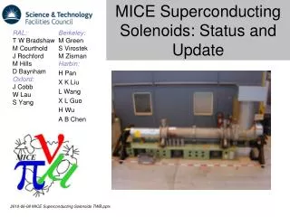
Spectrometer Solenoid Update Steve Gourlay For Steve Virostek Lawrence Berkeley National Lab
Topics • Latest magnet training results • Summary of 2nd magnet progress • Control system upgrade • Risks and mitigation
MICE Cooling Channel Layout Spectrometer Solenoid #1 Spectrometer Solenoid #2
Current Progress (1st magnet) • The first magnet (designated SS#2) has been successfully trained to full flip and solenoid mode currents • Current was maintained at full flip mode for a period of 24 hours with no quench • All five power supplies were used at various ramp rates and under computer control • Numerous improvements and fixes implemented on control and power supply systems • Improved cold mass heater control loop worked well • Cold mass is being held at 4K and full of LHe in preparation for upcoming 3D magnetic mapping
Working on Both Magnets Training complete Assembly
Recent Training Runs Target training current achieved (283 A) HTS lead failure After warmup, control sys mods, and cooldown Vent line blockage After warmup, HTS lead replace and cooldown
2nd Magnet Progress • The cold mass/shield assembly is complete, MLI wrapped and suspended in the vacuum vessel • Installation of thecryocooler tower is complete • First stage cooler connections to the thermal shield are being installed • Vacuum vessel end plates are now being welded • LBNL mechanical technicians playing a key role in assembly (instrumentation, MLI wrap, HTS leads)
Control System Upgrade • A control system review was held at LBNL on December 11th and 12th, 2012 • The LBNL/MICE team developed improvements from the numerous review panel recommendations • The current system is more robust and capable of protecting the magnet from potential failures • A secondary goal of the upgrade was to move closer to the final system to be operated in the MICE hall
Control System Upgrade • Several of the primary upgrades: • Stand alone PID controller for the cold mass heater circuit with current monitor • Alarm handler to the control software • Gas bottle backup system prevents negative cold mass pressure; improved durability ofPRV’s • New current shunts directly measure the current in each coil
Power Supplies and Control • Power Supplies • New 500 A supply for center and end coils • 5 supplies fully integrated • System verified during recent training runs • Control rack • Many upgrades installed • New heater control loop • UPS added
Upcoming Tasks • 3D magnetic bore mapping of first unit using CERN developed system to begin later in May with iron shielding disk in place • Second unit assembly to be completed in next two to three weeks • After vacuum pumpout of 2nd magnet, cooldown and training to start in June • Shipping of fully commissioned magnets to RAL planned for July and September
Risks and Mitigation • SS controls operational readiness certification • Lack of a complete, fully operational and integrated control system led to previous system failures • Some risk remains as the final system to be implemented at RAL is still being developed • Mitigation: numerous upgrades have been implemented and testing during SS#2 training; additional improvements are under way, and the system will be tested during SS#2 mapping and SS#1 training/mapping
Risks and Mitigation (cont’d) • SS#2 re-train and re-test • Addition of the iron shield for mapping will alter the coil forces and possibly lead to the need for some re-training • Magnet has always required re-training after warm-up and subsequent cool-down • Mitigation: • The cold mass has been maintained at 4K since the completion of the training runs, avoiding any re-training due to thermal expansion/contraction • The forces due to the shield are only a fraction of the nominal inter-coil forces • The training procedure is well established
Risks and Mitigation (cont’d) • SS#2 operational failure with iron shield • Some risk presented as iron shield has never been fitted to the vacuum vessel, and magnet has never been operated with the shield in place • Mitigation: • Iron shield supports designed with conservative safety factors and adequate adjustment capability; fast turnaround modifications possible using Wang NMR and/or LBNL shop • Magnetic forces on cold mass supports are only a fraction of the calculated loads present during operation with other MICE magnets in place; cold mass supports designed and load tested 10% beyond operational requirements
Risks and Mitigation (cont’d) • SS#1 train and test • SS#1 represents a newly modified and assembled system that has never been tested in this configuration • Risk areas include: coil windings, cold leads, HTS lead connections, heat leaks, other mechanical systems • Mitigation: • The SS#1 cold mass has been previously trained to ~200 A • The design and as-built configuration of SS#1 is identical to that of SS#2 • The same technician crew that assembled SS#2 is also working on completing SS#1
Risks and Mitigation (cont’d) • SS#1 operational failure with iron shield • The risks and mitigation are the same as those for SS#2 • All training and testing of SS#1 will likely be carried out with the shield in place
Coupling Coils Steve Gourlay For Allan DeMello
CouplingCoil Cold Mass • Winding of cold mass coils #2, #3 and #4 by QiHuan Company (Beijing, China) • Preparation cold mass coils #2, #3 and #4 at LBNL • Magnetic test of cold mass coils #2, #3 and #4 at FNAL • Risks to schedule • Delay getting superconductor to China • Problem with winding process at QiHuan • Leak in cooling pipe after pressure test at LBNL • Damage during shipping to FNAL • Problem during magnetic testing
CouplingCoil Cryostat • LBNL mechanical shop is in the process of fabricating the first cryostat • Estimated completion on 7-1-2013 • Drawings will be updated to reflect the “as built” cryostat • Determine fabricator for the additional 2 cryostats • Risks to schedule • Delay in fabrication process • Vessel not vacuum tight • Damage during shipping to FNAL Single Cavity Vacuum Vessel Exploded View
Coupling Coil Thermal Shield • Thermal shield design is nearly complete • Drawings have been red lined but not updated • Some SINAP parts/drawings will need to be revised for better manufacturability • LBNL shops will fabricate the first thermal shield • Risks to schedule • Delay getting drawings finished • Problem with fabrication process • Damage during shipping to FNAL
Cold Mass Fully Assembled (at FNAL) • Reservoir/cooling circuit installation complete • Cold mass support brackets and band installed • Cold mass wrapped with MLI • Risks to schedule • Delay getting bands fabricated • Leak in reservoir circuit
CoolingCircuit • Finalize cooling circuit design • Create detail fabrication drawings • Fabrication of component parts • Assemble components • Risks to schedule • Delay fabrication of component parts • Unforeseen problem during assembly
CCM Prototype Assembly at FNAL • Cold mass prepared for integration with cryostat • Mount cold mass support bracket and bands • Wrap cold mass in MLI • Assemble thermal shield around cold mass • Wrap assembly in MLI • Insert cold mass into cryostat • Attach cold mass support bands to cryostat • Align magnet in the cryostat • Weld on cryostat tower and inner bore • Risks to schedule • Unforeseen problem during assembly • Vessel not vacuum tight
CCM Prototype Assembly at FNAL • Weld tower assembly to cryostat • Assemble upper cooling circuit • Attach upper cooling circuit to the cold mass cooling circuit • Risks to schedule • Unforeseen problem during assembly • Cooling circuit leak due to welding error • Vacuum leak in cryostat
CCM Prototype Assembly at FNAL • Add cryocoolers to cooling circuit • Coupling coil training and testing • Risks to schedule • Magnet does not get to cold enough for superconducting operation with cryocoolers