Download
1 / 65
650 likes | 782 Views
Wormhole RTR FPGAs with Distributed Configuration Decompression. CSE-670 Final Project Presentation A Joint Project Presentation by: Ali Mustafa Zaidi Mustafa Imran Ali. Introduction. “An FPGA configuration architecture supporting distributed control and fast context switching.”

E N D
Wormhole RTR FPGAs with Distributed Configuration Decompression CSE-670 Final Project Presentation A Joint Project Presentation by: Ali Mustafa Zaidi Mustafa Imran Ali
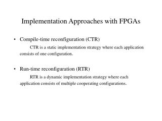
Introduction • “An FPGA configuration architecture supporting distributed control and fast context switching.” • Aim of Joint Project: • Explore the potential for dynamically reconfiguring FPGAs by adapting the WRTR Approach • Enable High Speed Reconfiguration using: • Optimized Logic-Blocks and • Distributed Configuration Decompression techniques • Study focuses on Datapath-oriented FPGAs
Project Methodology • In depth study of issues. • Definition of basic Architecture models. • Definition of Area models (for estimation of relative overhead w.r.t other RTR schemes). • Design of Reconfigurable systems around designed Architecture models. • Identification of FPGA resource allocation methods • For distributing FPGA area between multiple applications/hosts (at runtime, compile-time, or system design-time). • Selection of Benchmarks for testing and simulation of various approaches. • Experimentation with WRTR systems and corresponding PRTR system without distributed configuration (i.e. single host/application) for comparison of baseline performance. • Evaluate resource utilization, and normalized reconfiguration overhead etc. • Experimentation with all systems with distributed configurations (i.e. multiple hosts/applications). The PRTR systems’ configuration port will be time multiplexed between the various applications. • Evaluate resource utilization, and normalized reconfiguration overhead etc.
Configuration Issues with Ultra-high Density FPGAs • FPGA densities rising dramatically with process technology improvements. • Configuration time for serial method becoming prohibitively large. • FPGAs are increasingly used as compute engines, implementing data-intensive portions of applications directly in Hardware. • Lack of efficient method for dynamic reconfiguration of large FPGAs will lead to inefficient utilization of the available resources.
Scalability Issues with Multi-context RTR • Concept: While one plane is operating, configure the other planes serially. • Latency hidden by overlapping configuration with computation • As FPGA size, and thus configuration time grows, Multi context becomes less effective in hiding latency • Configuring more bits in parallel for each context is only a stop-gap solution. • Only so many pins can be dedicated to configuration • Overheads in the Multi-context approach: • Number of SRAM cells used for configuration grow linearly with number of contexts • Multiplexing Circuitry associated with each configurable unit • Global, low-skew context select wires.
Scalability Issues with Partial RTR • Concept: The Configuration memory is Addressable like standard Random Access Memory. • Overheads in PRTR Approach: • Long global cell-select and data busses required – • area overhead, • issues with single cycle signal-transmission as wires grow relative to logic. • Vertical and Horizontal Decoding circuitry – represent centralized control resource. • Can be accessed only sequentially by different user applications (one app at a time) • Potential for underutilization of hardware as FPGA density increases. • One solution could be to design the RAM as a multi-ported memory • But area of RAM increases quadratically with increase in number of ports. • Only so many dedicated configuration ports can be provided • Not a long-term scalable solution.
What is Wormhole RTR • WRTR is a method for reconfiguring a configurable device in an entirely distributed fashion. • Routing and configuration handled at local instead of global level.
Advertised Benefits of WRTR • WRTR is a distributed paradigm • Allows different parts of same resource to be independently configured simultaneously. • Dramatically increases the configuration bandwidth of a device. • Lack of centralized controller means: • Fewer single point failures that can lead to total system failure (e.g. a broken configuration pin) • Increased resilience: routing around faults – improving chip yields ? • Distributed control provides scalability • Eliminates configuration bottleneck.
Origins of Wormhole RTR • Concept Developed in late 90s at Virginia Tech. • Intended as a method of rapidly creating and modifying ‘custom computational pathways’ using a distributed control scheme. • Essence of WRTR concept: • Independent self-steering streams. • Streams carried both programming information as well as operand data • Streams interact with architecture to perform computation. (see DIAGRAM)
Origins of Wormhole RTR • Programming information configures both the pathway of stream through the system, as well as the operations performed by computational elements along the path. • Heterogeneity of architectures is supported by these streams. • Runtime determination of path of stream is possible, allowing allocation of resources as they become available.
Adapting WRTR for conventional FPGAs • Our aims • To achieve Fast, Parallel Reconfiguration • With minimum area overhead • And minimum constraints imposed on the underlying FPGA Architecture. • Configuration Architecture is completely decoupled from the FPGA Architecture. • WRTR model is used as inspiration for developing a new paradigm for dynamic reconfiguration • Not necessary that WRTR method is followed to the letter
Issues Associated with using WRTR for Conventional FPGAs • Original WRTR was intended for Coarse-grained dataflow architectures with localized communications • Thus operand data was appended to the streams immediately after the programming header. • In conventional FPGAs, dataflow patterns are unrelated to configuration flow, and there is no restriction of localizing communications. • Therefore Wormhole routing is used only for configuration (cannot be used for data).
Issues Associated with using WRTR for Conventional FPGAs • The original model was intended to establish linear pipelines through system. • This makes run-time direction determination feasible. • However, for conventional FPGAs, the functions implemented have arbitrary structures. • Configuration stream can not change direction arbitrarily (i.e. fixed at compile-time).
Issues Associated with using WRTR for Conventional FPGAs • Due to the need for large number of configuration ports, I/O ports must be shared/multiplexed • thus active circuits may need to be stalled to load configurations. • Should not be a severe issue for high-performance computing oriented tasks. • Should impose minimum constraints on the underlying FPGA architecture • Constraints applicable in an FPGA with WRTR are same as those for any PRTR architecture.
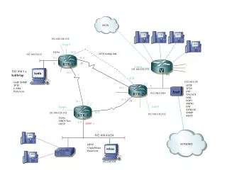
A Possible System Architecture for a WRTR FPGA • Many configuration/IO ports, divided between multiple host processors. (See Diagram) • Internally, FPGA divided into partitions, useable by each of the hosts. • Partition boundaries may be determined at system design time, or at runtime, based on requirements of each host at any given time
The various WRTR Models derived • Our aim was to devise a high-speed, distributed configuration model with all the benefits of the original WRTR concept, but with minimum overhead. • To this end, 3 models have been devised: • Basic: with Full Internal Routing • Second: with Perimeter-only Routing. • Third: Packetized, or parallel configuration streams, with no Internal Routing.
Basic WRTR Model: with Internal Routing • Each configurable block or “tile” is accompanied by a simple configuration Stream Router. See Diagram • Overhead scales linearly with FPGA Size. • Expected Issues with this model • Complicated router, arbitration overhead and prioritization, potential for deadlock conditions etc. • May be restricted to coarser grained designs. • Without data routing, do we really need internal routing?
Second: WRTR with Perimeter-only Routing • Primary requirement for achieving parallel configuration is multiple input ports. • Internal Routing not a mandatory requirement. • So why not restrict routing to chip boundary? (See Diagram) • Overhead scaling improved (similar to PRTR Model) • Highlights: • Finer granularity for configuration achievable • Significantly lower overheads as FPGA sizes grow (ratio of perimeter to area) • Issues • Longer time required to reach parts of FPGA as FPGA Size grows. • Reduced configuration parallelism because of potentially greater arbitration delays at boundary Routers.
Third: Packet based distribution of Configuration • One solution to the increased boundary arbitration issues: use packets instead of streams. (See Diagram) • A single configuration from each application is generated as a stream (a worm) similar to previous models. • Before entering device, configuration packets from different streams are grouped according to their target rows.
Third: Packet based distribution of Configuration • Benefit: No need at all for Routers in the fabric itself. • Drawbacks: • Increases overhead on the host system • Implies a centralized external controller • Or a limited crossbar interconnect within the FPGA • Parallel Reconfiguration still possible, but with limited multitasking. • This model may be considered for embedded systems, with low configuration parallelism, but high resource requirements.
Basic Area Model • Baseline model required to identify overheads associated with each PRTR model. • Basic Building block: (See Diagram) • A basic Array of SRAM Cells • Configured by arbitrary number of scan chains. • Assumptions for a fair comparison of overhead: • Each RTR model studied has exactly the same amount of Logic resources to configure (rows and columns). • Each model can be configured at exactly the same granularity. • The given array of logic resources (see Diagram) has an area equivalent to a serially configurable FPGA. • AREA of Basic Model = (A* B) * (x * y)
The PRTR FPGA Area Model • Please See Diagram • Configuration Granularity decided by A and B • AREA = Area of Basic model + Overheads • Overheads = • Area of ‘log2(x)-to-x’ Row-select decoder + • Area of ‘log2(y)-to-y’ n-bit Column De-multiplexer + • Area of 1 n-bit bus * y
The basic WRTR FPGA Area Model • Please See Diagram • AREA = Area of Basic Model + Overheads • Overheads = • Area of 1 n-bit bus * 2x + • Area of 1 n-bit bus * 2y + • Area of 1 4-D Router block * [x * y].
The Perimeter Routing WRTR FPGA Area Model • Please See Diagram • AREA = Area of Basic Model + Overheads • Overheads = • Area of 1 n-bit bus * 2x + • Area of 1 n-bit bus * 2y + • Area of 1 3-D Router block * [2(x + y) – 1] • This model can also be made one dimensional to further reduce overheads. (other constraints will apply)
The Packet based WRTR FPGA Area Model • Please See Diagram • AREA = Area of Basic Model + Overheads • Overheads = • Area of 1 n-bit bus * 2x + • Area of 1 n-bit bus * 2y • Additional overheads may appear in host system. • This model can also be made one dimensional to further reduce overheads. (other constraints will apply)
Parameters defined and their Impact • The number of Busses (x and y) • Number of Busses varies with reconfiguration granularity. • For fixed logic capacity, A and B increase with decreasing x and y, i.e. coarser granularity. • Impact of coarser granularity: • Reduced overhead ? • Reduced reconfiguration flexibility • Increased reconfiguration time per block • Thus it is better to have finer granularity • The Width of the busses (n-bits) • Smaller the width, smaller the overhead (for fixed number of busses) • Longer Reconfiguration times.
Parameters defined and their Impact • It is possible to achieve finer granularity without increasing overhead at the cost of bus width (and hence reconfiguration time per block) • Impact of Coarse grained vs. Fine grained configurability – Methods of Handling hazards in the underlying FPGA fabric. • Coarse grained configuration places minimum constraints on FPGA architecture • Fine-grained reconfiguration is subject to all issues associated with Partial RTR Systems.
Approaches to Router Design • Active Routing Mechanism • Similar to conventional networks • Routing of streams depends on stream-specified destination, as well as network metrics (e.g. congestion, deadlock) • Hazards and conflicts may be dealt with at Run-time. • Significantly complicated routing logic required. • Most likely will be restricted to very coarse grained systems. • Passive Routing Mechanism • Routing of streams depends only on stream-specified direction • Hazards and conflicts avoided by compile time optimization. • We have selected the Passive Routing Mechanism for our WRTR Models
Passive Router Details • Must be able to handle streams from 4 different directions. • Streams from different directions only stalled if there is a conflict in outgoing direction. • Includes mechanisms for stalling streams in case of conflict etc. • Detecting and Applying back-pressure • Routing Circuitry for one port is defined (see Diagram) • For a 4D router, this design is replicated 4 times • For a 3D router, this design is replicated 3 times
Utilizing Variable Length Configuration Mechanisms Support Hardware and Logic Block Issues
Configuration Overhead • Configuration data is huge for large FPGAs • Has to be reduced in order to have fast context switching
Configuration Overhead Minimization • Initial pointers in this direction • Variable Length Configurations • Default Configuration on Power-up
Variable Length Configurations • Ideally • Change only minimum number of bits for a new configuration • Utilize the idea of short configurations for frequently used configurations • Start from a default configuration and change minimum bits to reconfigure to a new state
Hurdles • Logic blocks always require full configurations to be specified – configuration sizes cannot be varied • Knowing only what to change requires keeping track of what was configured before – difficult issue in multiple dynamic applications switching • A default power-up configuration can hardly be useful for all application cases
Configuration Overhead Minimization • How to do it? • Remove redundancy in configuration data or “compact” the contents of configuration stream • Result? This will minimize the information required to be conveyed during configuration or reconfiguration • Configuration Compression • Applying “some” sort of compression to the configuration data stream
Configuration Decompression Approaches • Centralized Approach • Decompress the configuration stream at the boundary of the FPGA • Distributed Approach – New Paradigm • Decompress the stream at the boundary of the Logic Blocks or Logic Cluster
Centralized Approach • Advantage • Requires hardware only at the boundary of the device from where the configuration data enters the device • Significant reduction in configuration size can be achieved • Runlength Coding and Lemple-Ziv based compression used • Examples • Atmel 6000 Series • Zhiyuan Li, Scott Hauck, “Configuration Compression for Virtex FPGAs”,IEEE Symposium on FPGAs for Custom Computing Machines, 2001
Centralized Approach • Limitations • More efficient variable length coding not easy to use because of the large number of symbol possibilities • It is difficult to quantify symbols in the configuration stream of heterogeneous devices which can have different types of blocks
Decentralized Approach • Advantages • Decompressing at the logic block boundary enables configurations to be easily symbolized and hence VLC to be used • In other words, we know what exactly we are coding so Huffman like codes can be used based on the frequency of configuration occurrences • Also has advantages specific to Wormhole RTR – discussed next
Decentralized Approach • Limitations • The decompression hardware has to be replicated • Optimality Issue: Decompression hardware should be amortized over how much programmable logic area? • In other words, granularity of the logic area should be determined for optimal cost/benefit ratio
Suitability of Decentralized Approach to WRTR • If worms are decompressed at the boundary, large internal worms lengths will result • This leads to greater internal worm lengths and greater issues to arbitration and worm blockages • Decentralized approach thus favors shorter worm lengths and parallel worms to traverse with less blockages
Variable Length Configuration • Overall idea • Frequently used configurations of a logic block should have small sized codes • Variable length coding such as Huffman coding can be adapted
Configuration Frequency Analysis • How to decide upon the frequency? • Hardwired? By the designer through benchmarks analysis? • Generic? Done by software generating the configuration stream
Continued… • Hardwired determination will be inferior – no large benefit gained due to variations in applications • Software that generates the configuration can optimally identify a given number of frequently used configuration according to set of applications to be executed • Code determination should be done by software generating the configurations for optimal codes
Decoding Hardware Approaches • Huffman coding the configurations • A Hardwired Huffman Decoder • Adaptive Decoder (code table can be changed) • Using a Table of Frequently used configurations and address Decoder • Huffman Coding the Table Addresses • Static Coding • Adaptive Coding
Decoding Hardware Features • Static Huffman Decoders • Lower compression • Coding Configurations • Requires a very wide decoder • Using an Address Decoder only • Reduced hardware but less compression (fixed sized codes) • Coding the Decoder Inputs • Requires a relatively smaller Huffman decoder
Some points to Note • Decompression approach is decoupled from any specific logic block architecture • Though certain logic blocks will favor more compression (discussed later) • Not every possible configuration will be coded. Especially random logic portions will require all the bits to be transmitted • A special code will prefix the random logic configuration to identify it to be handled separately
Logic Block Selection • High Level Issues • Should be Datapath Oriented • Efficient support for random logic implementation • High functionality with minimum configuration bits to support dense implementation with reconfiguration overhead reduction • Well defined datapath functionality (configuration) to aid in the quantification of frequently used configuration idea