Download
1 / 196
2.75k likes | 3.62k Views
Functions of a Pump. Transfer fluid between two points. Produce required flow rate. Produce required pressure. Pump - Facts. Pump changes both velocity and pressure of the fluid. Pump only adds to the system energy.

E N D
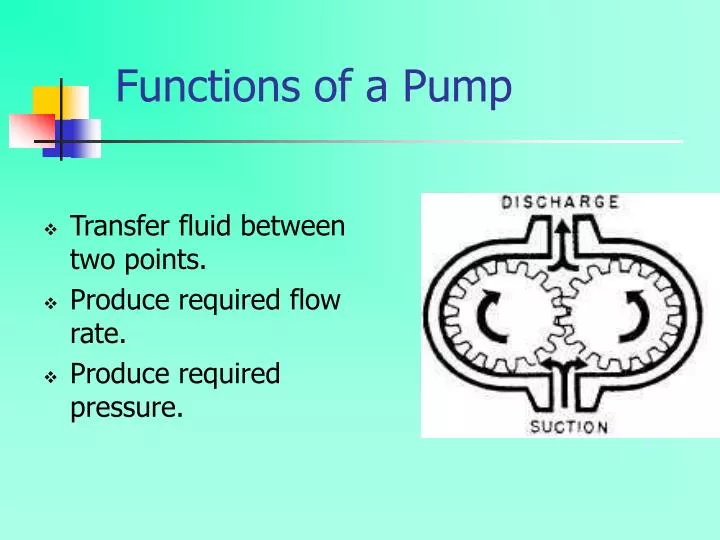
Functions of a Pump Transfer fluid between two points. Produce required flow rate. Produce required pressure.
Pump - Facts • Pump changes both velocity and pressure of the fluid. • Pump only adds to the system energy. • Power supplied to the pump is to transfer fluid at specified flow rate and pressure by overcoming resistance in the pump and the system. • A pump does not create pressure, it only provides flow. Pressure is just an indication of the amount of resistance to the flow.
Pumps and Viscosity of Fluid Handled. • Viscosity of the fluid pumped must be within the range specified in the pump design. • Reciprocating Displacement pumps can handle any required viscosity. • Rotary Positive Displacement Pumps ( Common- Gear and Screw ) are used for intermediate range of viscosities. • Centrifugal Pumps are used for Medium to Low range of viscosities. • Onboard ships, permission should be obtained before any fluids are moved, which might affect the stability of the ship.
Centrifugal Pump (Rotodynamic) • Centrifugal pump distinguished from Positive displacement pump ------ • Requirement of relative velocity between the fluid and the impeller. • Shaped casing or diverging nozzle converts kinetic energy into pressure energy. • Liquid in the impeller and casing essential for pump operation.
Centrifugal Pump- Theory • The energy changes occur in a centrifugal pump by virtue of two main parts of the pump. • The Impeller – The rotating part that converts driverenergy into kinetic energy. • The volute or Diffuser – The stationary part that converts the kinetic energy into pressure energy. • The process liquid enters the suction nozzle and then into the eye of the impeller. Impeller spins the liquid sitting in the cavities between the vanes, outwards and provides centrifugal acceleration. As liquid leaves the eye of the impeller, a low pressure area is created, causing more liquid to flow towards the inlet. Because the impeller blades are curved, the fluid is pushed in a tangential and radial direction by the centrifugal forces.
Centrifugal Pump- Theory • The process liquid enters the suction nozzle and then into the eye of the impeller. Impeller spins the liquid sitting in the cavities between the vanes, outwards and provides centrifugal acceleration. As liquid leaves the eye of the impeller, a low pressure area is created, causing more liquid to flow towards the inlet. Because the impeller blades are curved, the fluid is pushed in a tangential and radial direction by the centrifugal forces.
Centrifugal Pump - Theory The amount of energy given to the liquid is proportional to the velocity at the edge or vane tip of the impeller. The faster the impeller revolves or bigger the impeller is, then higher will be the velocity of the liquid at the vane tip and greater the energy imparted to the liquid.
Centrifugal Pump – Theory. The kinetic energy of a liquid coming out of an impeller is harnessed by creating a resistance to the flow. The first resistance is created by pump volute casing, which catches the liquid and slows it down. In the discharge nozzle, the liquid further decelerates and its velocity is converted to pressure.
Centrifugal Pump - Head The pressure at any point in a liquid can be thought of as being caused by a vertical column of the liquid due to its weight. The height of this column is called the static head and is expressed in terms of meters of liquid. Head is a measurement of height of a liquid column that a pump could create from kinetic energy imparted to the liquid. Imagine a pipe shooting a jet of water straight up into the air, the height the water goes up would be the head.
Centrifugal Pump - Vapour Pressure Vapor pressure is the pressure at which a liquid and its vapor co-exist in equilibrium, at a given temperature. Vaporization begins when the vapor pressure of the liquid at the operating temperature equals the external system pressure, which in an open system always equal to the atmospheric pressure. Any decrease in external pressure or rise in operating temperature can induce vaporization and the pump stops pumping.
Centrifugal Pump – Velocity Head Velocity Head refers to the energy of a liquid as a result of its motion at some velocity,‘ V ‘. It is the equivalent head in meters through which the water would have to fall to acquire the same velocity or the head necessary to accelerate the water. Velocity head is insignificant in most high head systems, but it can be large in low head systems.
Factors Affecting Suction Lift • Temperature and volatility of the fluid • Pressure exerted on the free side of the liquid. • Friction Losses at entrances, bends and pipes in the suction system.
Priming of Centrifugal Pump. Priming is the process of removing Air/Vapour and filling the suction piping, impeller and pump casing with the fluid. METHODS OF PRIMING • Liquid ring air-pump. • Ejector. • Reciprocating Pump. – Obsolete.
Types of Impellers, With Respect to Flow. • Radial flow. • Axial flow. • Mixed flow.
For low flows and high pressures, the action of the impeller is largely radial. For higher flows and lower discharge pressures, the direction of the flow within the pump is more nearly parallel to the axis of the shaft, and the pump is said to have an axial flow. The impeller in this case acts as a propeller. The transition from one set of flow conditions to the other is gradual, and for intermediate conditions, the device is called a mixed-flow pump. Conical designs also featured in the transition from radial to axial flow conditions. Specific Speed Range Pump Type Below 5,000 Radial Flow Pumps 4,000 - 10,000 Mixed Flow Pumps 9,000 - 15,000 Axial Flow Pumps
Types of Impellers With Respect to Construction. • Open (with partial shrouds for strength. - - For abrasive liquids with suspended solids. • Semi-Open - - For viscous liquids. • Enclosed - - For clear liquids.
Types of Centrifugal Pumps With Respect to the Construction of the Casing. • Volute • Diffuser • Regenerative
Volute Casing • It is like a curved funnel increasing in area to the discharge port, which converts velocity energy into pressure energy. Also it helps to balance the hydraulic pressure on the shaft of the pump- occurs at the recommended capacity. Running at lower capacity can put lateral stress on pump shaft, increase wear-and-tear on the seals, bearings and on the shaft itself.
Diffuser or Circular Casing • It has stationary diffusion vanes, surrounding the impeller periphery that convert velocity energy into pressure energy. • Conventionally the diffusers are applied to multistage pumps.
Regenerative(turbine Pump) • The impeller , which has very tight axial clearance and uses pump channel rings. Liquid entering the channel from the inlet is picked up immediately by the vanes on both sides of the impeller and pumped through the channel by shearing action. The process is repeated over and over with each pass imparting more energy until the liquid is discharged.
Centrifugal Pump – Operational Summary • THREE INDICATIONS IF A PUMP IS CAVITATING • Noise. • Fluctuating discharge pressure and flow. • Fluctuating pump motor current.
Steps to Stop cavitation of a Pump • Increase pressure at the suction of the pump. • Reduce the temperature of the liquid being pumped. • Reduce head losses in the suction piping. • Reduce the flow rate through the pump. • Reduce the speed of the pump impeller.
Effects of cavitation. • Degraded pump performance. • Metal gets corroded seen as small pittings. • Audiable rattling or crackling sounds which can reach a pitch of dangerous vibrations. • Damage to pump impeller, bearings, wear rings and seals.
Pump Operation - Facts • To avoid pump cavitaion, NPSH available must be greater than NPSH required. • NPSH available is the difference between the pump suction pressure and the saturation pressure of the liquid being pumped. • Cavitation is the process of the formation and subsequent collapse of vapor bubbles in a pump. • Gas binding of a centrifugal pump is a condition where the pump casing is filled with gases or vapors to the point where the impeller is no longer able to contact enough fluid to function correctly.