Download
1 / 1
10 likes | 126 Views
.75”. .25”. 1”. 2”. 5”. 10.65”. 2”. .0625”. 6061-T0. Aluminum. 6061-T651. Aluminum. This picture shows the safety factor associated with the maximum sheer stress on the bridge. This picture shows the safety factor associated with the Equivalent von-Mises stress on the bridge.

E N D
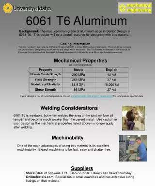
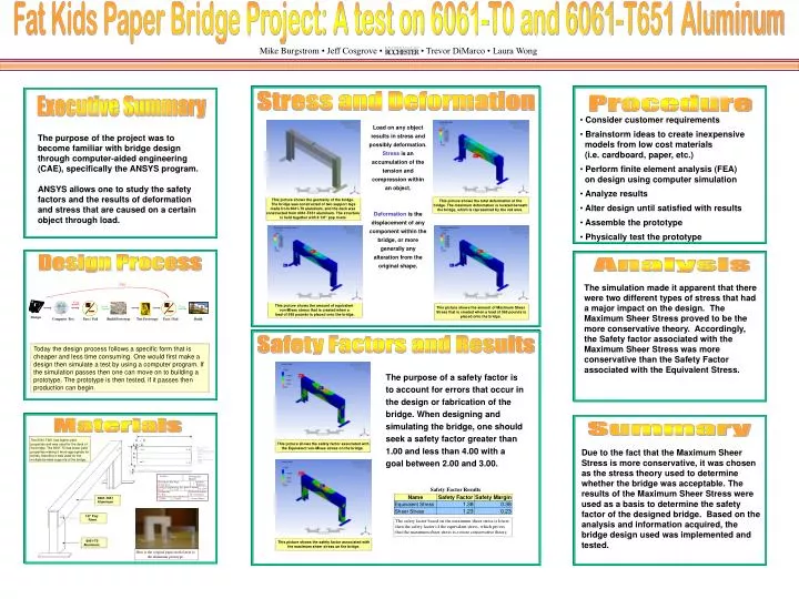
.75” .25” 1” 2” 5” 10.65” 2” .0625” 6061-T0 Aluminum 6061-T651 Aluminum This picture shows the safety factor associated with the maximum sheer stress on the bridge. This picture shows the safety factor associated with the Equivalent von-Mises stress on the bridge. Design Process Today the design process follows a specific form that is cheaper and less time consuming. One would first make a design then simulate a test by using a computer program. If the simulation passes then one can move on to building a prototype. The prototype is then tested, if it passes then production can begin. Notes: Material 6061-T651 sheet Aluminum Drill holes when flat Fold 90 degrees in two places along dotted lines to form parts as shown in drawing FK-003. Both bent legs should be same length Break sharp edges Shear to size All dimensions in Inch Units Unless otherwise indicated, use default tolerances x.x +/- .050” x.xx +/- .010” x.xxx +/- .005” Angles +/- 2 degrees 1/8" Pop Rivet Here is the original paper model next to the aluminum prototype. Fat Kids Paper Bridge Project: A test on 6061-T0 and 6061-T651 Aluminum Mike Burgstrom • Jeff Cosgrove • • Trevor DiMarco • Laura Wong Stress and Deformation Procedure Executive Summary • Consider customer requirements • Brainstorm ideas to create inexpensive models from low cost materials (i.e. cardboard, paper, etc.) • Perform finite element analysis (FEA) on design using computer simulation • Analyze results • Alter design until satisfied with results • Assemble the prototype • Physically test the prototype Load on any object results in stress and possibly deformation. Stress is an accumulation of the tension and compression within an object. Deformation is the displacement of any component within the bridge, or more generally any alteration from the original shape. The purpose of the project was to become familiar with bridge design through computer-aided engineering (CAE), specifically the ANSYS program. ANSYS allows one to study the safety factors and the results of deformation and stress that are caused on a certain object through load. This picture shows the geometry of the bridge. The bridge was constructed of two support legs made from 6061-T0 aluminum, and the deck was constructed from 6061-T651 aluminum. The structure is held together with 8 1/8” pop rivets. This picture shows the total deformation of the bridge. The maximum deformation is located beneath the bridge, which is represented by the red area. Analysis Fail The simulation made it apparent that there were two different types of stress that had a major impact on the design. The Maximum Sheer Stress proved to be the more conservative theory. Accordingly, the Safety factor associated with the Maximum Sheer Stress was more conservative than the Safety Factor associated with the Equivalent Stress. Fail This picture shows the amount of equivalent von-Mises stress that is created when a load of 565 pounds is placed onto the bridge. Pass Pass This picture shows the amount of Maximum Sheer Stress that is created when a load of 565 pounds is placed onto the bridge. Design Computer Test Pass / Fail Test Prototype Pass / Fail Build Build Prototype Safety Factors and Results The purpose of a safety factor is to account for errors that occur in the design or fabrication of the bridge. When designing and simulating the bridge, one should seek a safety factor greater than 1.00 and less than 4.00 with a goal between 2.00 and 3.00. Materials Summary The 6061-T651 has higher yield properties and was used for the deck of the bridge. The 6061-T0 has lower yield properties making it more appropriate for bends, therefore it was used for the multiple bended supports of the bridge. Due to the fact that the Maximum Sheer Stress is more conservative, it was chosen as the stress theory used to determine whether the bridge was acceptable. The results of the Maximum Sheer Stress were used as a basis to determine the safety factor of the designed bridge. Based on the analysis and information acquired, the bridge design used was implemented and tested. Fat Kids Drawing No. FK-001 Descriptive Part Name Quantity Required 1 Bridge Deck Drawing Type Drawing Size Scale as Drawn Safety Factor Results Scale as Printed 1:1,1indrawing=1inpart Detail A 8 x10 1:1 =100% Designed by Checked by Engineer Fat Kids M. E. Engineer Drawing Issue Date Date of This Revision 12/6/04 12/6/04 Engineer Phone # The safety factor based on the maximum sheer stress is lower then the safety factor of the equivalent stress, which proves that the maximum sheer stress is a more conservative theory.