Download
1 / 12
120 likes | 259 Views
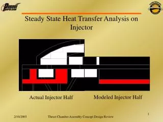
Steady State Heat Transfer Analysis on Injector. Modeled Injector Half. Actual Injector Half. Outline of Procedure Used. Get Chamber Properties from NASA code Density Sonic Velocity Viscosity Specific Heat Thermal Conductivity Pick Mach number tangent to surface: 0.4

E N D
Steady State Heat Transfer Analysis on Injector Modeled Injector Half Actual Injector Half Thrust Chamber Assembly Concept Design Review
Outline of Procedure Used • Get Chamber Properties from NASA code • Density • Sonic Velocity • Viscosity • Specific Heat • Thermal Conductivity • Pick Mach number tangent to surface: 0.4 • Steady state heat transfer iteration for gas-side wall temperature for oxidizer and fuel sections • Compute fuel pressure loss through injector Thrust Chamber Assembly Concept Design Review
Fuel-Side Analysis Fuel Flow Copper Wall Camber Gases Convection Conduction Convection Thrust Chamber Assembly Concept Design Review
Gas-side Wall Temperature Iteration Steps • Guess Gas-Side Wall Temperature, Twg • Bartz Equation: Thrust Chamber Assembly Concept Design Review
Fuel-Side Iteration • Gas-Side Heat Flux: • Fuel-side Wall Temperature: Thrust Chamber Assembly Concept Design Review
Fuel-Side Iteration • Seider-Tate Forced Convection: • Correlations as a function of temperature at 350psi for transport and physical properties of Propene from NIST Chemistry Web book • Temperature at previous position used, Tinitial=405°R Thrust Chamber Assembly Concept Design Review
Fuel-Side Iteration • Fuel-side Heat Flux: • If fuel-side heat flux = gas-side heat flux, continue, else choose another guess for Twg • Fuel Temperature at current position: Thrust Chamber Assembly Concept Design Review
Fuel-Side Iteration • Pressure Iteration: • Move to next axial position and repeat Thrust Chamber Assembly Concept Design Review
Oxidizer-Side Analysis Stagnant O2 Fixed Temperature, Liquid O2 = 162°R Copper Wall Conduction Convection Camber Gases Copper Wall • Same procedure as fuel-side except Two is fixed at liquid oxygen temperature Thrust Chamber Assembly Concept Design Review
Fuel-Side Results, M = 0.4 dTwg ≈ 82°R Thrust Chamber Assembly Concept Design Review
Overall Results, M = 0.4 Thrust Chamber Assembly Concept Design Review
Fuel Convective Heat Transfer Coefficient Thrust Chamber Assembly Concept Design Review