Download
1 / 25
250 likes | 813 Views
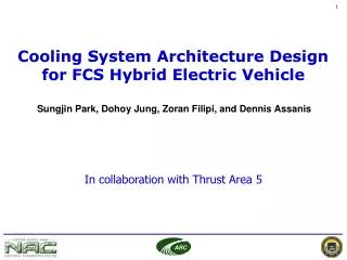
Cooling System Architecture Design for FCS Hybrid Electric Vehicle. Sungjin Park, Dohoy Jung, Zoran Filipi, and Dennis Assanis The University of Michigan. In collaboration with Thrust Area 5. Outline. Background Motivation and Challenges Objectives SHEV Configuration

E N D
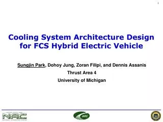
Cooling System Architecture Design for FCS Hybrid Electric Vehicle Sungjin Park, Dohoy Jung, Zoran Filipi, and Dennis Assanis The University of Michigan In collaboration with Thrust Area 5
Outline • Background • Motivation and Challenges • Objectives • SHEV Configuration • Cooling System Component Modeling • Cooling System Architecture • Results and Discussion • Summary and Future Plan
Army Ground Vehicle Propulsion Challenges • Cooling • Cooling • Cooling • Fuel Effects • Filtration The Army vehicle cooling point is high tractive effort to weight under desert-like operating conditions (ex. 5 ton wheeled vehicle ~0.6 while 15 ton tracked vehicle ~0.7 both at 120 F ambient) This slide is from the keynote by Dr. Pete Schihl during the 2007 ARC annual conference
Future Combat System (FCS) • Series Hybrid Electric Vehicle (SHEV) is under development for the automotive platform of FCS. • Improved fuel economy • Greater electric power requirements for advanced weapon system • Exportable electric power • Enhanced low speed maneuverability • Low acoustic signature and stealth operation • Pulse power necessary to drive weapon/mobility/communication/protective systems • Better maintenance: non-mechanical coupling of the power generation unit with drive train architecture
Case Study Objectives • Develop a guideline/methodology for cooling system architecture selection for the SHEV • Develop cooling system models for optional architectures. • Explore and demonstrate proper architectures and strategies for thermal management of hybridized powertrain • Optimize the cooling system and component design for performance, size and minimal parasitic loss
Motivation and Challenges • SHEVs need additional components • Generator, Motor, Battery, and Power bus • SHEVs also have a dedicated cooling system for the hybrid components with different requirements • Cooling system design for SHEV requires more strategic approach • Multiple cooling circuits due to additional components • Different operating temperature and driving modes • Numerical approach is an efficient way for complicated HEV cooling system design and development.
Vehicle Cooling system for Future Combat System (FCS): Challenges SHEV Cooling System • Heavy-duty operation (20 ton, 400-500 hp vehicle) • Severe military operation under extreme ambient conditions • Shielded cooling system for survivability • Complicated cooling system architecture in SHEV due to the additional heat sources with various requirements • Vehicle cooling system operation and performance varies with powertrain operation, control, and driving conditions. Conventional Cooling System
Objectives • Develop an efficient cooling system architecture for the SHEV and Optimize the cooling system design using numerical approach: • Configure a SHEV model using VESIM • Model the components of the cooling system for SHEVs • Develop cooling system model integrating the components models • Evaluate the cooling system designs and architectures • Optimize the cooling system • SHEVs need effective cooling system design that has least impact on fuel economy and cost
SHEV Configuration (VESIM) Generator Power Bus Engine Controller Battery Motor Vehicle
Power Management of Hybrid Vehicle Charging/Electric Drive mode Braking mode Discharging mode • Engine/Generator is the prime power source • When battery SOC is lower than limit, engine supplies additional power to charge the battery • Once the power demand is determined, engine is operated at most efficient point • Battery is the prime power source • When power demand exceeds battery ability, the engine is activated to supplement power demand • Regenerative braking is activated to absorb braking power • When the braking power is larger than motor or battery limits, friction braking is used
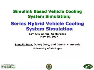
Vehicle Cooling System Simulation (VCSS) SIMULINK Based Vehicle Cooling System Simulation
Vehicle Cooling System Simulation (VCSS) SIMULINK Based Vehicle Cooling System Simulation
Vehicle Cooling System Simulation (VCSS) SIMULINK Based Vehicle Cooling System Simulation
Vehicle Cooling System Simulation (VCSS) SIMULINK Based Vehicle Cooling System Simulation
Cooling System Architecture Development Architecture A • Separate cooling circuit is added for electric components. • Electric pumps are used for electric heat sources to separate the cooling circuit for electric components from engine module • The radiators are arranged in the order of control target temperature of heat source which is cooled by the radiator
Cooling System Architecture Development Architecture A Architecture B Control Target Temp. of Heat Sources • Cooling circuit for electric components is further divided into two circuits based on control target temperatures. • Electric pumps are used for electric heat sources to separate the cooling circuit for electric components from engine module • The radiators are arranged in the order of control target temperature of heat source which is cooled by the radiator.
Cooling System Architecture Development Architecture C Operation Group of Heat Sources Cooling Module 1 Cooling Module 2 (1)The heat source components are allocated into two cooling modules based on the operating groups to minimize redundant operation of the cooling fan. (2) The condenser used for the air conditioning of the compartment is placed in the cooling module where the heat load is relatively lower.
SIMULINK Based Vehicle Cooling System SimulationVehicle Cooling System Simulation (VCSS) Cooling circuit for electric components A/C Condenser Electric Components Parallel Cooling Circuit Coolant pump Radiator1 Cooling circuit for engine module Charge Air Cooler Parallel Cooling Circuit Oil Cooler Thermostat Engine Engine Block Radiator2 Coolant pump Fan & cooling air
Sequential SHEV-Cooling System Simulation • Operation history of each HEV component from VESIM is fed into Cooling system Model as input. • Better computational efficiency compared to co-simulation Driving schedule Hybrid Vehicle Model Cooling System Model
Cooling System Test Conditions • Three driving were selected to size the components of cooling system and to evaluate cooling system design performance Off-Road Maximum Speed (Governed) Grade Load Ambient Temperature : 40 oC Road profile for off-road
Driving Schedulefor the Evaluation of Cooling System • Realistic driving schedule is needed to evaluate the cooling system • City + Cross country driving schedule is used Operation Group of Heat Sources City + Cross country Driving Schedule Heat Rejection Rate of Each Component over Driving Schedule
Power Consumption and Cooling Performance during Driving Schedule Electric Component Temperature Power Consumption
Cooling System Power Consumptions Portion of Cooling System Power Consumption in Engine Power Improvement of Power Consumption by Cooling System Redesign
Summary and Future Plan • SHEV model was configured with the previously developed VESIM. • Cooling system model for the SHEV was developed. • The results show that strategic approach to cooling system architectural design of SHEVs can reduce the power consumption and enhance the performance significantly. • Co-simulation of VESIM and Cooling system model is needed to evaluate • Fuel economy impact • Interaction between the powertrain system and cooling system