Download
1 / 23
240 likes | 784 Views
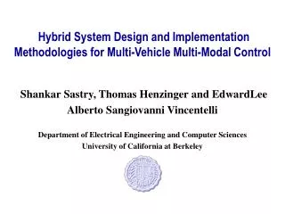
Cooling System Architecture Design for FCS Hybrid Electric Vehicle. Sungjin Park , Dohoy Jung, Zoran Filipi, and Dennis Assanis Thrust Area 4 University of Michigan The University of Michigan. Outline. Motivation and Challenges Objectives Cooling System Architecture Design

E N D
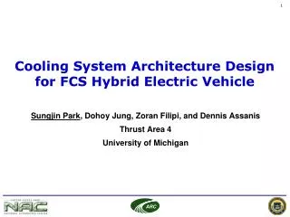
Cooling System Architecture Design for FCS Hybrid Electric Vehicle Sungjin Park, Dohoy Jung, Zoran Filipi, and Dennis Assanis Thrust Area 4 University of Michigan The University of Michigan
Outline • Motivation and Challenges • Objectives • Cooling System Architecture Design • Cooling System Component Sizing • Results and Discussion • Summary and Future Plan
I C M Motivation and Challenges • Cooling system is critical issue for combat vehicle’s survivability • Series Hybrid Electric Vehicle for FCS. • Additional powertrain components for SHEV • Additional heat sources need additional cooling circuit, pump, fan , sensors, and controllers • Complicated cooling system architecture in SHEV due to the additional heat sources with various requirements and various vehicle driving modes Power Bus/ Controller Motors Generator - + Engine Battery Sprocket
Objectives • Develop a guideline/methodology for an efficient cooling system architecture selection for FCS SHEV using modeling and simulation capability • Criteria for cooling system architecture design selection: • Cooling requirements • Parasitic power consumption • Thermal shock (temperature fluctuation) • Packaging
Cooling System Architecture Development Architecture A - Separate cooling circuit is added for electric components.
Cooling System Architecture Development Architecture A Architecture B Control Target Temp. of Heat Sources - Cooling circuit for electric components is further divided into two circuits based on control target temperatures.
Cooling System Architecture Development Architecture C Operation Group of Heat Sources Cooling Module 1 Cooling Module 2 - The heat source components are allocated into two cooling modules based on the operating groups to minimize redundant operation of the cooling fan.
Vehicle Cooling System Simulation (VECSS) Component Models Generator Motor Power Bus A/C Condenser Coolant pump Radiator1 Charge Air Cooler Engine Thermostat Oil Cooler Radiator2 Coolant pump Fan & cooling air
I C M SHEV Configuration (VESIM) Vehicle Specification Generator Power Bus Engine Battery Motor Controller Vehicle Power Bus/ Controller Motors Generator - + Engine Battery Sprocket Framework from the ARC Case Study: Integrated hybrid vehicle simulation (SAE 2001-01-2793)
Sequential SHEV-Cooling System Simulation • Operation history of each HEV component from VESIM is fed into Cooling system Model as input. • Better computational efficiency compared to co-simulation Driving schedule Hybrid Vehicle Model Cooling System Model
Component Sizing Step 1 : Initial Scaling • Radiator and pump are the main component that determines cooling capacity • Initially, the sizes of radiator and pump are estimated by scaling from well established cooling system Heat rejection at radiator: • Therefore, • Scaling Factor (a) Hybrid vehicle cooling system criteria for initial scaling
Component Sizing Step 2 : Radiator Packaging • Radiator occupies largest area • The radiator size is limited by the physical dimensions of the vehicle( 20ton 0ff-road tracked vehicle ~ light tank) • Packaging constraint is determined by considering vehicle size and radiator size of compatible vehicle (radiators are confined in 1.2x0.75 rectangle) • The heights of all radiators are fixed at 0.75m for the convenience of radiator assembly
Component Sizing Step 2 : Radiator Thickness • Radiator thickness is another design factor • Optimal radiator thickness found by cooling power vs heat transfer test • Radiator thickness is designed not to exceed 100mm Radiator Test Device Radiator
Component Sizing Step 3 : Pump Scaling • If radiator size is changed by the packaging constraint, cooling pump size should be rescaled • First estimation don’t guarantee the cooling performance for vehicle cooling requirement • Heat rejection at radiator: • Therefore, or Pump scaling: Hybrid vehicle cooling system criteria for pump scaling
Component Sizing Step 4 : Severe Condition Simulation • Three driving conditions were simulated to size the components of cooling system and to evaluate cooling system design performance Ambient Temperature : 48.8 oC (120F) Grade Load (30mi/h, 7%) Maximum Speed (Governed) Grade Load (20mi/h, 12%)
Component Sizing Step 4 : Severe Condition Simulation • Detailed design is conducted by trial and error test under severe condition (20mph, 12% grade) • Higher coolant temperature close to control target temperature of component is recommended to reduce the radiator size • Temperature distribution in components / Coolant temperature change in cooling circuit 1 2 1 2
Driving Schedulefor the Evaluation of Cooling System • Cooling system architectures are evaluated for representative mission. Heavy duty urban cycle + Cross country driving schedule
Cooling Performance during Driving Schedule Generator Motor Power Bus Electric Component Temperature
Cooling System Power Consumptions 58% A B C 66% A B 42% C 70% A B 30% C 33% Improvement of Power Consumption by Cooling System Redesign
Summary • SHEV model was configured with the previously developed VESIM and cooling system model for the SHEV was developed. • The results show that the cooling system architecture of the SHEV should be developed considering various cooling requirements of powertrain components, power management strategy, performance, and parasitic power consumption. • It is also demonstrated that a numerical model of the SHEV cooling system is an efficient tool to assess design concepts and architectures of the system during the early stage of system development
Future Plan • Co-simulation to study the effect of cooling system on the fuel economy of SHEVs and the interaction between the vehicle and cooling system.
Acknowledgement • Automotive Research Center (ARC) • General Dynamics, Land Systems (GDLS)