Download
1 / 40
420 likes | 772 Views
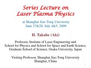
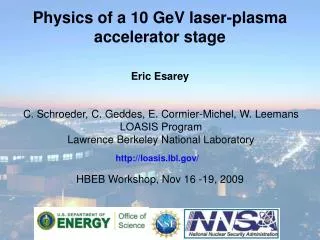
Physics of a 10 GeV laser-plasma accelerator stage. Eric Esarey. C. Schroeder, C. Geddes, E. Cormier-Michel, W. Leemans LOASIS Program Lawrence Berkeley National Laboratory. http://loasis.lbl.gov/. HBEB Workshop, Nov 16 -19, 2009. Outline. Regimes of laser-plasma accelerators

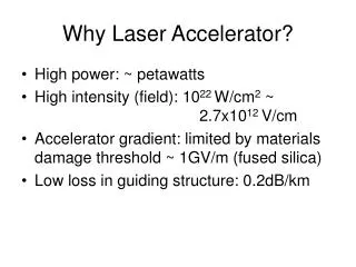
E N D
Physics of a 10 GeV laser-plasma accelerator stage Eric Esarey C. Schroeder, C. Geddes, E. Cormier-Michel, W. Leemans LOASIS Program Lawrence Berkeley National Laboratory http://loasis.lbl.gov/ HBEB Workshop, Nov 16 -19, 2009
Outline • Regimes of laser-plasma accelerators • Quasi-linear and highly nonlinear (blowout) • Limits to single-stage energy gain in a LPA • Diffraction, dephasing, depletion • Scaling laws for single-stage energy gain • Analytic theory and fluid simulations • Conceptual design of a laser-plasma collider at 1 TeV • Based on 10 GeV stages • Requires tens of J laser pulses at tens of kHz • Plasma and laser tailoring to improve performance • Longitudinal density tapering to eliminate dephasing • Higher-order laser modes to control transverse fields Ref: Esarey, Schroeder,Leemans, Reviews of Modern Physics (2009)
B.A. Shadwick et al., IEEE PS. 2002 Laser Wakefield Accelerator (LWFA) Standard regime (LWFA): pulse duration matches plasma period Ultrahigh axial electric fields => Compact electron accelerators Plasma wakefields Ez > 10 GV/m, fast waves (Conventional RF accelerators Ez ~ 10 MV/m) Plasma channel: Guides laser pulse and supports plasma wave Tajima, Dawson (79); Gorbunov, Kirsanov (87); Sprangle, Esarey et al. (88)
Conceptual LPA Collider • Based on 10 GeV modules • Quasi-linear wake: e- and e+ • Driven by 40 J, 130 fs pulses • 80 cm plasma channels (1017 cm-3) • Staging & coupling modules • Requires high rep-rate (10’s kHz) • Requires development of high average power lasers (100’s kW) Leemans & Esarey, Physics Today, March 2009
Basic design of a laser-plasma accelerator: single-stage limited by laser energy • Laser pulse length determined by plasma density • kpsz ≤ 1, sz~ lp ~ n-1/2 • Wakefield regime determined by laser intensity • Linear (a0<1) or blowout (a0>1) • Determines bunch parameters via beam loading • Ex: a0 = 1 for I0 = 2x10¹⁸ W/cm2 and 0 = 0.8 m • Accelerating field determined by density and laser intensity • Ez ~ (a02/4)(1+a02/2)-1/2n1/2 ~ 10 GV/m • Energy gain determined by laser energy via depletion* • Laser: Present CPA technology 10’s J/pulse laser Ez wake *Shadwick, Schroeder, Esarey, Phys. Plasmas (2009)
Linear & blowout regimes: e+/e- acceleration • Blowout regime • high field • very asymmetric • focuses e- • defocuses e+ • self-trapping • Quasilinear • linear: symmetric e+/e- • high a0 desired for gradient • too high enters bubble • a0 ~1-2 good compromise • dark current free a0=1 a0=4 Axial field e- accel e+ accel e- accel e+ accel run 405 Plasma density e+ focus Transverse field e- focus e+ focus e- focus
DW = Ez . L Limits to acceleration length: diffraction • “3D”: Diffraction, Dephasing, Depletion • Diffraction of laser pulse • ZR = p r02/l0~ 2 cm, ZR<< Ldephase < Ldeplete • Solution: Density channels • Parabolic channel guides gaussian modes • Channel depth: Dn [cm-3] = 1020 / (r0[mm])2 ~ 2x1016 cm-3 W.P. Leemans et al, IEEE Trans. Plasmas Sci. (1996); Esarey et al., Phys. Fluids (1993)
DW = Ez . L Limits to Acceleration Length: dephasing • Dephasing: e- outrun wake, • Phase velocity: vp/c ≈ vg/c = 1- l02/2lp2 • Ldephase (1-vg/c) = lp/2, • Ldephase = lp3/l02 ~ n-3/2 ~ 1.6 m • Solution: density tapering vp<c e- beam Ez laser vp<c e- beam Ez laser
Density Tapering: Phase Lock e- • For a0 ~ 1, Ldephase may be < Ldeplete • Phase velocity depends on density • Phase position ~ lp~ n-1/2 • Taper density to tune wake velocity • Depletion then limits e- energy gain n1 laser e- beam Ez n2>n1 laser e- beam Ez density Katsouleas, PRA (1986); Sprangle et al, PRE (2001)
Alternative tapering options:Step density transition (2) (1) (3) (1) (2) • Maintains near-resonance of plasma response with laser • Experimental realization: staged accelerator sections (3) C. Schroeder et al.
DW = Ez . L Limits to acceleration length: depletion • Depletion: laser loses energy to wake • Energy balance: EL2sz = Ez2 Ldeplete • Linear limit a02 << 1: Ldeplete = a0-2 Ldephase >> Ldephase • Nonlinear limit a02 >> 1: Ldeplete ~ Ldephase laser laser Ez Ez Solution: staging
Rate of laser energy deposition • Developed theory of nonlinear short-pulse laser evolution. • Derived general energy evolution equation valid for any laser intensity and pulse shape • Scale separation (laser frequency >> plasma frequency) • Neglect backward going waves (Raman backscatter) • Model plasma as cold fluid • Apply quasi-static approximation (laser slowly varying compared to plasma response): characteristic accelerating field: Shadwick, Schroeder, Esarey, Physics of Plasmas (2009)
Nonlinear plasma wave excitation by a Gaussian laser pulse • Peak plasma wave driven by Gaussian laser insensitive to pulse duration (broad resonance) over intensity regime of interest
Pump depletion length independent of intensity for ultra-intense pulses Pump depletion length: Pump depletion length for near-resonant Gaussian laser pulse: • Characteristic length scale independent of intensity for relativistically-intense laser pulses
laser Depletion: necessitates multiple stages • Single stage energy gain limited by laser energy depletion • Diffraction limitation: mitigated by transverse plasma density tailoring • Dephasing limitation: mitigated by longitudinal plasma density tailoring Depletion Length: Accelerating field: Energy gain (linear regime): • Ex: Wstage = 10 GeV for I= 1018 W/cm2 and n= 1017 cm-3 • Multiple-stages for controlled acceleration to high energy: + channel …
Laser pulse evolution ωpt=500 plasma density Laser field Laser energy evolution: accelerating field ωpt=1500 ωpt=2500 ωpt=3500 • Laser evolution interplay between laser intensity steepening, laser frequency red-shifting, energy depletion Shadwick, Schroeder, Esarey, Physics of Plasmas (2009)
Longitudinal e-bunch dynamics: energy spread minimum near dephasing Fluid plasma + e-bunch described by moments (includes beam loading) Laser Wake Momentum e-bunch Energy spread Position, kp(z-ct) Energy spread Initial: / = 0.3% at = 100 Final: / = 0.01% at = 3000 Time, pt B.A. Shadwick et al.
Scaling laws from fluid code: dephasing/depletion lengths & energy gain Fraction of laser energy at dephasing length • Quasi-linear: a0 ~ 1 • Dephasing ~ depletion • Good efficiency Independent of k/kp • Fix laser parameters (a0, kpL0, kpr0), increase (k/kp) to increase energy • Energy and dephasing length from 1D fluid simulations • a0 =1: max = 0.7(k/kp)2 , kpLdp= 4(k/kp)2 • a0 =1.5: max = 1.3(k/kp)2 , kpLdp= 3.5(k/kp)2 • a0 =2: max = 2(k/kp)2 , kpLdp= 3(k/kp)2
Point designs: 10 and 100 GeV • Laser power: P[GW] = 21.5(a0r0/)2 , Critical power: Pc[GW] = 17(k/kp)2, P/Pc = (a0kpr0)2 /32. • All assume: kpL0 = 2, m
Parameter design for GeV and beyond W. Lu et al., Phys Rev STAB (2007) Note: Channel guiding: 60% and 40%; Self-guiding: 0%; external injection: 60%; self-injection: 40% and 0% P/Pc=0.7 for 60% case, and 2 for 40% case
Beam loading simulations predicts 300-500 pC for 10 GeV stages • Beam loading theoretical limit • e-bunch wake = laser wake • Linear theory , kpsz < 1, kpsr ~ 1 • Nb ~ 9x9 (n0 16 cm-3)-1/2 (Ez/E0) • Ex.: Nb= 3x10⁹ (0.5 nC) for n017 cm-3 and Ez/E0=1 ~constant field inside bunch Quasi-linear beam loading matches linear theory + 2D * 3D -- theory • VORPAL PIC simulations • 500 pC at 1017 cm-3 for kpL=2, kpsr~ 2 • 10% of laser energy to electrons • Bunch length & profile alters field inside bunch • flatten field across bunch – reduces DE • focusing must be matched for emittance • Ongoing: precise controlw/shaped bunches * Cormier-Michel et al, Proc. AAC 2008, **Katsouleas PRA 1986
Beam loading: tailored bunches for high efficiency • Linear theory • Symmetric bunches • Energy spread ~ N/Nmax • Efficiency ~ N/Nmax (2 - N/Nmax) • Ex: Spread100%, Effic100% as NNmax • Triangle bunches (high density in front) • Load wake with constant Ez inside bunch • Can minimize energy spread with high efficiency (at reduced Ez) • Requires density tapering to phase lock bunches T. Katsouleas et al., Part. Accel. 22, 81 (1987) Blowout regime: M. Tzoufras, et al., PRL (2008)
Adjusting length flattens field for minimum energy spread Beam loading versus bunch length • Gaussian bunch • Length adjusts wake loading within bunch • Bunch & laser wakefield nearly balanced even for symmetric bunches • Flattens field across bunch – reduces DE • Shaped bunch can further reduce DE no charge L = 0.085 m L = 0.85 m L = 0.51 m kpr = 0.3 scaled charge 60pC
Axial density taper locks bunch phase:improves gain and reduces DE for e+,e- Compensate dephasing by changing lp~ n1/2 Linear taper at kpL=2 produces 4x gain Positron acceleration ~symmetric Ongoing: optimize taper, emittance matching initial kpL=1 results : 50% depletion, 10 GeV gain for 300 pC, 2.5%FWHM Spectra at dephasing __e- --e+ no taper Taper 0 #/GeV/c [A.U.] 1 0 Gain [GeV/c at 1019/cc] 0.12 0 Scale Gain [GeV/c at 1017/cc] 12 • gain in stages with kpL=2 at 1019 cm-3 • 50% beam loaded -kpr = 1, kpL = 0.5 • 3D charge: 22.5pC • 225pC, 9 GeV gain, 4% FWHM, at 1017 cm-3
Matched electron beam spot size is small • Matched beam spot size • linear regime • bubble regime • matched beam < 1 mm (<< lp ~ 100 mm) for g = 20,000 (10 GeV), n0 = 1017 cm-3, en = 1 mm mrad • Limits electron beam charge and quality • Increase sy for higher charge, with nbpeak small • In linear regime kb2 ∝ E⊥∝ ∇⊥a2 • Reduce transverse field gradient to increase matched beam radius
Higher order laser mode to tailor transverse wakefield • Linear regime : E⊥/E0 ~ ∇⊥a2/2 • Add first order Hermite-Gaussian mode in 2D a2 = a02 HG02 + a12 HG12 a2 a1/a0 HG0 HG1 0.7 0.5 0.4 0 y/r0 gaussian y/r0 Ey/E0 first order hermite-gaussian mode exact solutions of the paraxial wave equation analytic calculation (low a) no channel y/r0
Higher order mode propagation in plasma channel Low intensity propagation in matched plasma channel integrated transverse intensity profile • Hermite-Gaussian modes exact solution of the linear paraxial wave eq • Guiding in plasma channel is the same for all modes • Dn = Dnc = 1/prer02 • Phase / group velocity different for each mode • Intensity modulation when modes co-propagate HG02 (HG0 + HG1)2 kpy (HG02 + HG12) HG12 kpy a0=0.1 a0=0.1 a1=0.1 a1=0.5a0 • Solution • Use cross-polarization • Use different frequencies kbeat= m/ZR kbeat>> kp
Transverse field tailoring in the quasi linear regime • Wakefield driven by higher order modes in the quasi linear regime a0=1 • Transverse field flattened by flat top laser profile • Mode propagation to depletion • short pulse kpL = 1 minimizes pulse variations • shallower plasma channel compensates for self-focusing 30 30 30 laser envelope Ey Ex 0.3 0.03 high order mode reduces Ey, @ y = -1 mm (y/w0 ~ 0.1) ___ Ex/E0 ---- Ey/E0 higher order mode ….. Ey/E0 gaussian Y(µm) Y(µm) Y(µm) -30 -30 -30 -0.03 -0.3 X(µm) X(µm) X(µm) 200 240 200 X(µm) 200 225 200 225 225 30 30 30 30 Ey Ex laser envelope integrated laser intensity profile Y(µm) Y(µm) Y(µm) Y(µm) -30 -30 -30 -30 X(µm) X(µm) X(µm) 1935 1980 0 X(mm) 1935 1965 1935 1965 4
Summary • Design considerations for a laser-plasma collider module • Diffraction, Dephasing, Depletion: necessitates staging • Conceptual design of laser-plasma collider at 1 TeV • Quasi-linear wake (a0 ~ 1), electrons and positrons • 10 GeV modules: Laser pulse 40 J, 130 fs, 10 kHz • Requires development of 100’s kW average power (10 kHz) lasers • Requires research on LWFA physics and staging technology • Demonstrate low emittance, high charge, short e-bunches • Plasma and laser tailoring to improve performance • Longitudinal density tapering to eliminate dephasing • Higher-order laser modes to control transverse fields • BELLA will give us the capabilities to study 10 GeV stages
Proper choice of plasma density and staging minimizes main linac length • Linac length will be determined by staging technology • Number of stages: Laser LPA Lc Lacc Lstage • Conventional optics (~10 m) • Plasma mirror (~10 cm)
0.5 TeV γ-γ Collider Example Plasma density scalings: Stage density scalings: Collider density scalings (for fixed luminosity):
10 GeV gain with efficient loading accessible on BELLA 40 J 10 GeV ~300pC 0.5 J 0.4 GeV ~50pC • 300 pC 10 GeV stage with taper@kpL=1 • Demonstrated control by shaping laser, plasma, ebunch • Initial efforts reduced DE10%2.5% • shaped bunches & taper in progress • matching bunch emittance, shape to structure
Emittance matched bunch radius << lp for Gaussian-laser linear, nonlinear regimes • can reduce loading efficiency and/or cause ion motion • Linear regime: Fields shaped via laser mode to compensate emittance* • demonstrated propagation, channel compensation Laser mode controls transverse field, controls bunch emittance matching Laser Envelope Scale 1 Propagation to depletion Ex@ 5.1018 scale 60GV/m Ey @ 5.1018 scale 20GV/m 30 30 30 10 Y(µm) Y(µm) Y(µm) --kpx --10 -30 -30 -30 1110 1070 0 ct(ZR) 5 1070 1095 1070 1095 X(µm) X(µm) X(µm) • Ongoing: compensation of beam loaded fields * Cormier-Michel et al, in prep.
2D PIC simulations demonstrate a factor 3 in matched electron beam radius • With higher order mode and delay beam radius can be increased x3 charge x9 • Beam radius limited by linear region of focusing field • Can increase flat top region by using higher order modes 0.3 • simulation at n0 = 5x1018 cm-3 • matched emittance 0.014 mm mrad varies < 1% • scaled parameters at 1017 cm-3 • sy = 2 mm • en = 0.1 mm mrad 0.2 sy (mm) 0.1 0.0 2 3 0 1 ct (mm) —·— gaussian + hermite gaussian with delay —— gaussian + hermite gaussian ______gaussian pulse …….. gaussian pulse (unmatched)
Energy depletion: Analytic result in good agreement with numerical solution Analytic result (- - - - - -) :
Fluid simulations: verify and quantify scaling laws Axial wakefield GeV-class example: • 1D fluid code (B.A. Shadwick) • Standard LWFA regime • a0 = 1.5, k0/kp = 40, kp L =2 • Laser: 0.8 mm, 5x10¹⁸ W/cm2, 30 fs • Plasma: 1018 cm-3, 3 cm Energy gain Laser pulse 1 GeV =z-ct E. Esarey et al., AAC Proc 2004
Fluid simulation of scaled BELLA point design n monemtum Ez energy spread bunch distance • Scaled point design example: 1D fluid code (B.A. Shadwick) • Quasi-linear LWFA regime • a0 = 1.0, k0/kp = 40, kp L =2 • Laser: 0.8 mm, 2x10¹⁸ W/cm2, 40 fs • Plasma: 1018 cm-3, • Bunch: kpsz = 0.5, Dg/g = 0.9% (initial), 0.05% (final@ 0.5 GeV)
Reducing energy spread and emittance requires controlled injection Transverse motion • Self-injection experiments have been in bubble regime: • Cannot tune injection and acceleration separately • Emittance degraded due to off-axis injection and high transverse fields. • Energy spread degraded due to lack of control over trapping 5 Y[µm] -5 800 X[µm] 2000 ⇒ Use injector based on controlled trapping at lower wake amplitude and separately tunable acceleration stage to reduce emittance and energy spread