Download
1 / 16
170 likes | 322 Views
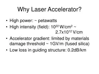
Why Laser Accelerator?. High power: ~ petawatts High intensity (field): 10 22 W/cm 2 ~ 2.7x10 12 V/cm Accelerator gradient: limited by materials damage threshold ~ 1GV/m (fused silica) Low loss in guiding structure: 0.2dB/km. losses ~ 0.2 dB/km at l =1.55µm (amplifiers every

E N D
Why Laser Accelerator? • High power: ~ petawatts • High intensity (field): 1022 W/cm2 ~ 2.7x10¹² V/cm • Accelerator gradient: limited by materials damage threshold ~ 1GV/m (fused silica) • Low loss in guiding structure: 0.2dB/km
losses ~ 0.2 dB/km at l=1.55µm (amplifiers every 50–100km) more complex profiles to tune dispersion “high” index doped-silica core n ~ 1.46 “LP01” confined mode field diameter ~ 8µm protective polymer sheath Optical Fibers Today silica cladding n ~ 1.45
Solid-core Holey Fibers solid core holey cladding forms effective low-index material Can have much higher contrast than doped silica… strong confinement = enhanced nonlinearities, birefringence, … [ J. C. Knight et al., Opt. Lett.21, 1547 (1996) ]
1000x better loss/nonlinear limits (from density) Hollow-core Bandgap Fibers Bragg fiber [ Yeh et al., 1978 ] 1d crystal + omnidirectional = OmniGuides 2d crystal Photonic Crystal PCF [ Knight et al., 1998 ]
Experimental Air-guiding PCF [ R. F. Cregan et al., Science285, 1537 (1999) ] 10µm 5µm
silica glass tube (cm’s) (outer cladding) ~50 µm fiber draw fuse & draw ~1 mm Fabrication: Air-guiding PCF
3 1 compatible materials Thermal evaporation 2 Make pre-form (“scale model”) chalcogenide glass, n ~ 2.8 + polymer (or oxide), n ~ 1.5 fiber drawing Fabrication: Bragg Fiber [Y. Fink et al., MIT ]
white/grey = chalco/polymer A Drawn Bandgap Fiber [Y. Fink et al., MIT ]
Acceleration Mode in Bragg Fiber • b=k0=2p/l • a/l=1 • nhigh=2.6 • nlow=1.6 • Er=-jp r/l Ez • Radiation loss: 0.2dB/km • 20-pair of layers
Small Surface Field Structure • b=0.79253k0 • a/l=1 • nhigh=2.6 • nlow=1.6 • Er=0 at r0=a
Dispersion Relation: TM01 1mm No perturbation
1mm Dispersion Relation: TM01
Surface Field Perturbation in Cladding (Metal) Perturbation in Core pa/l=2.2 pa/l=3.14
Summery • Hollow core fiber is able to confine acceleration mode (TM01, vp=c) • Uniform light wave guiding does not reduce Er (pr/aEz) • Looking for structures that can be made for acceleration (polymer microstructured fiber, tapered fiber)
Other Challenges • light coupling, (evanescent coupling) • mode excitation, • imperfection vs. mode mixing • …