Download
1 / 1
10 likes | 134 Views
Post-Linac Beam Transport and Collimation for THE UK’s New Light Source project. D. Angal-Kalinin, J. L. Fernandez-Hernando, F. Jackson, B. Muratori, ASTeC/STFC, Daresbury Laboratory, U.K. BEAM SPREADER

E N D
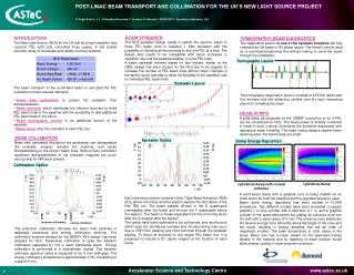
Post-Linac Beam Transport and Collimation for THE UK’s New Light Source project D. Angal-Kalinin, J. L. Fernandez-Hernando, F. Jackson, B. Muratori, ASTeC/STFC, Daresbury Laboratory, U.K. BEAM SPREADER The NLS spreader design needs to switch the electron beam to three FEL beam lines in baseline 1 KHz operation with the possibility of diverting all the bunches to any one FEL at a time. The design also needs to be compatible with future increases in repetition rate and the possible addition of extra FEL lines. A beam spreader scheme based on fast kickers, similar to the LBNL design has been chosen for the NLS due to its capacity to increase the number of FEL beam lines without major changes in the facility layout and also to allow full flexibility in the repetition rate for individual FEL beam lines. Each extraction section consists of two Triple Bend Achromat (TBA) arcs, where the kicker and the septum replace the first dipole of the first TBA arc. The beam passes off-axis in the D quadrupole immediately after the kicker and through the F quadrupole before the septum. The beam is finally separated from the incoming beam after the D magnet after the septum The optics have been optimized to be achromatic and isochronous within each arc. Emittance increase and microbunching may occur due to CSR from passing very short bunches through the spreader dipoles. To divert all bunches to any single FEL beam line, it is proposed to include a DC dipole magnet at the location of each kicker. • INTRODUCTION • The New Light Source (NLS) for the UK will be a high repetition rate coherent FEL with fully controlled X-ray pulses. It will enable scientific study of nanoscale and rapidly evolving systems. • The beam transport of the acclerated beam to and past the FEL undulators contain several elements. • Beam halo collimation to protect the undulator from demagnetisation. • Beam spreader which distributes the electron bunches to three FEL beam lines in the baseline with the possibility to add additional FEL beam lines in the future. • Beam tomography section in an additional branch of the spreader. • Beam dump after the undulator in each FEL line. TOMOGRAPHY BEAM DIAGNOSTICS The diagnostics section in one of the spreader branches will fully characterize the beam in 6D phase space. The branch can be used as a commissioning/tuning line without having to send the beam through the undulators. The tomography diagnostics section consists of a FODO lattice with four screens and two deflecting cavities (one for each transverse plane) for streaking the beam. Tomography Layout Spreader Layout BEAM DUMPS A solid dump as proposed for the CEBAF tuning line or for X-FEL can be considered for NLS. The beam power is entirely contained in metal in such a dump, minimising the problems associated with radioactive water handling. The beam dump designs require beam rastering when the beam sizes are small. A solid beam dump with a graphite core is being studied as an initial option for both the baseline and the upgrade frequency case. Beam dump energy deposition has been studied in FLUKA simulations. Two different models have been simulated: a regular graphite 1 m long cylinder with a diameter of 1 m, and a graphite cylinder of the same dimensions but adding an entrance cone into the bulk with a base radius of 6 mm. The entrance cone distributes the beam’s energy more efficiently along the length of the cone and the dump, resulting in energy densities that are an order of magnitude smaller. The peak temperature in both cases is the same. Beam size has a major impact on the deposited energy density in the material and so rastering of beam position would allow simpler cooling or heat extraction solutions. BEAM COLLIMATION Beam halo generated throughout the accelerator can demagnetize the undulator magnet, activate the machine, and cause Bremsstrahlung in the photon beam lines. Without halo collimation significant demagnetization of the undulator magnets can occur very quickly for kW beam powers. The post-linac collimation removes the beam halo particles in dedicated transverse and energy collimation sections. The collimation scheme devised for the BESSY FEL design has been adopted for NLS. Transverse collimation is uses two betatron collimators separated by π/2 in each transverse plane. Energy collimation is performed in a downstream dogleg. The betatron collimator aperture optics is expected to be 4 mm (half-gap). The energy collimators acceptance is approximately ± 5%, translating to a gap of 4 mm. Spreader Optics Dump Energy Deposition Collimation Optics cylindrical dump cylindrical dump with conical entrance betatron collimators energy collimator