Download
1 / 31
310 likes | 358 Views
Learn about the complex control mechanisms and transport modes of the He3S Subsystem used for efficient injection, transport, and removal of polarized 3He gas in an nEDM system operating at ultra-low temperatures.

E N D
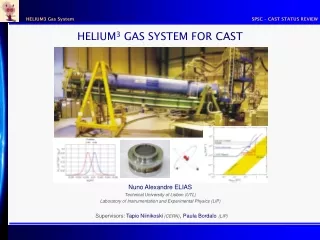
Helium-3 Services(He3S) Steven Williamson
Inject 3He Remove Unpolarized 3He Move 3He to Measurement Cell Measure He3S Subsystem Purpose • The working fluid for nEDM: • Polarized 3He in purified 4He (x3 = 10-10) • 0.30 to 0.55 K • For each measurement cycle 3He must be: • Polarized and injected efficiently into the 4He • Transported (with low polarization loss) to the measurement cells. • Removed after the polarization decays. • This cycle is controlled by elements of the He3S Subsystem. nEDM Preliminary Design Review – December 15-18, 2008 2
At T=0.3 K At T=0.5 K = 8 cm 3He moves as in a vacuum. Can use diffusion to transport 3He. = 0.2 cm 3He scatters from normal fluid (diffusion too slow) Create current in normal fluid (thermal gradient) • Use “heat flush” transport Complication: Need to vary operating temperature • To minimize geometric phase effect (and to check our understanding). • 3He mean free path varies rapidly with T 3He System must provide for both transport modes nEDM Preliminary Design Review – December 15-18, 2008 3
Optimum field: E > 50 kV/cm > 380 kVat 7.6 cm Another Complication: Pressurization • Measured breakdown voltage falls with temperature (vapor pressure) • Early R&D results: higher breakdown regained by pressurizing to 1 atm • More R&D will measure to T=0.45 K and study pressurization requirements, but… 3He System must provide compression to 1 atm nEDM Preliminary Design Review – December 15-18, 2008 4
10 11 6 8 7 9 5 4 3 2 1B 1A 3He System Block Diagram To Evaporator Vacuum Pump Pure 4He from External McClintock Purifier To Regeneration Pump • Cycle is controlled by: • Heaters (for heat flush) • Pressurizers • Valves Atomic Beam Source (ABS) Polarized 3He Collection System Cold Pure LHe Storage Evaporation Purifier Purifier Valve Cold Storage Valve IV1 Heater Collection Valve Volume Displace/ Pressurizer IV2 Valve Sequestration Volume Intermediate Volume 2 Intermediate Volume 1 Collection Level Valve IV2 “T” Valve IV1 “T” Valve SV Pressurizer IV1 Pressurizer Evaporator Valve IV1 Valve IV2 Heater Cell “T” Valve Evaporator Measurement Cell B Measurement Cell A Cell Isolation Valves nEDM Preliminary Design Review – December 15-18, 2008 5
10 11 6 8 7 9 5 4 3 2 1B 1A 3He System Block Diagram To Evaporator Vacuum Pump Pure 4He from External McClintock Purifier To Regeneration Pump Atomic Beam Source (ABS) Polarized 3He Collection System Cold Pure LHe Storage Evaporation Purifier Purifier Valve 0.35K Cold Storage Valve IV1 Heater Collection Valve Volume Displace/ Pressurizer IV2 Valve Sequestration Volume Intermediate Volume 2 Intermediate Volume 1 Collection Level Valve IV2 “T” Valve IV1 “T” Valve SV Pressurizer IV1 Pressurizer Evaporator Valve IV1 Valve IV2 Heater Cell “T” Valve Evaporator Injection (Note: assume we start with the rest of the system clean and at 1 atm.) Measurement Cell B Measurement Cell A Cell Isolation Valves nEDM Preliminary Design Review – December 15-18, 2008 6
10 11 6 8 7 9 5 4 3 2 1B 1A 3He System Block Diagram To Evaporator Vacuum Pump Pure 4He from External McClintock Purifier To Regeneration Pump Atomic Beam Source (ABS) Polarized 3He Collection System Cold Pure LHe Storage Evaporation Purifier Purifier Valve 0.35K Cold Storage Valve IV1 Heater Collection Valve Volume Displace/ Pressurizer IV2 Valve Sequestration Volume Intermediate Volume 2 Intermediate Volume 1 Collection Level Valve IV2 “T” Valve IV1 “T” Valve SV Pressurizer IV1 Pressurizer Evaporator Valve IV1 Valve IV2 Heater Cell “T” Valve Evaporator Diffuse to IV1 Measurement Cell B Measurement Cell A Cell Isolation Valves nEDM Preliminary Design Review – December 15-18, 2008 7
10 11 6 8 7 9 5 4 3 2 1B 1A 3He System Block Diagram To Evaporator Vacuum Pump Pure 4He from External McClintock Purifier To Regeneration Pump Atomic Beam Source (ABS) Polarized 3He Collection System Cold Pure LHe Storage Evaporation Purifier Purifier Valve Cold Storage Valve IV1 Heater Collection Valve Volume Displace/ Pressurizer IV2 Valve Sequestration Volume 1 atm Intermediate Volume 2 Intermediate Volume 1 Collection Level Valve IV2 “T” Valve IV1 “T” Valve SV Pressurizer IV1 Pressurizer Evaporator Valve IV1 Valve IV2 Heater Cell “T” Valve Evaporator Pressurize IV1 Measurement Cell B Measurement Cell A Cell Isolation Valves nEDM Preliminary Design Review – December 15-18, 2008 8
10 11 6 8 7 9 5 4 3 2 1B 1A 3He System Block Diagram To Evaporator Vacuum Pump Pure 4He from External McClintock Purifier To Regeneration Pump Atomic Beam Source (ABS) Polarized 3He Collection System Cold Pure LHe Storage Evaporation Purifier Purifier Valve Cold Storage Valve IV1 Heater Collection Valve Volume Displace/ Pressurizer IV2 Valve Sequestration Volume Intermediate Volume 2 Intermediate Volume 1 Collection Level Valve IV2 “T” Valve IV1 “T” Valve SV Pressurizer IV1 Pressurizer Evaporator Valve IV1 Valve IV2 Heater Cell “T” Valve Evaporator Diffuse from IV1 to Measurement Cells Measurement Cell B Measurement Cell A Cell Isolation Valves nEDM Preliminary Design Review – December 15-18, 2008 9
11 10 6 8 7 9 5 4 3 2 1B 1A 3He System Block Diagram To Evaporator Vacuum Pump Pure 4He from External McClintock Purifier To Regeneration Pump Atomic Beam Source (ABS) Polarized 3He Collection System Cold Pure LHe Storage Evaporation Purifier Purifier Valve Cold Storage Valve IV1 Heater Collection Valve Volume Displace/ Pressurizer IV2 Valve Sequestration Volume Intermediate Volume 2 Intermediate Volume 1 Collection Level Valve IV2 “T” Valve IV1 “T” Valve SV Pressurizer IV1 Pressurizer Evaporator Valve IV1 Valve 0.48K, 5 mW 0.52K, 9.9 mW IV2 Heater Cell “T” Valve Evaporator Heat Flush from IV1 to Measurement Cells Measurement Cell B Measurement Cell A Cell Isolation Valves 0.45K nEDM Preliminary Design Review – December 15-18, 2008 10
10 11 6 8 7 9 5 4 3 2 1B 1A 3He System Block Diagram To Evaporator Vacuum Pump Pure 4He from External McClintock Purifier To Regeneration Pump Atomic Beam Source (ABS) Polarized 3He Collection System Cold Pure LHe Storage Evaporation Purifier Purifier Valve Cold Storage Valve IV1 Heater Collection Valve Volume Displace/ Pressurizer IV2 Valve Sequestration Volume Intermediate Volume 2 Intermediate Volume 1 Collection Level Valve IV2 “T” Valve IV1 “T” Valve SV Pressurizer IV1 Pressurizer Evaporator Valve IV1 Valve IV2 Heater Cell “T” Valve Evaporator Measuring Measurement Cell B Measurement Cell A Cell Isolation Valves nEDM Preliminary Design Review – December 15-18, 2008 11
11 10 6 8 7 9 5 4 3 2 1B 1A 3He System Block Diagram To Evaporator Vacuum Pump Pure 4He from External McClintock Purifier To Regeneration Pump Atomic Beam Source (ABS) Polarized 3He Collection System Cold Pure LHe Storage Evaporation Purifier Purifier Valve Cold Storage Valve IV1 Heater Collection Valve Volume Displace/ Pressurizer IV2 Valve Sequestration Volume Intermediate Volume 2 Intermediate Volume 1 Collection Level Valve IV2 “T” Valve IV1 “T” Valve SV Pressurizer IV1 Pressurizer Evaporator Valve IV1 Valve 0.44K, 5 mW IV2 Heater 0.41K Cell “T” Valve Evaporator Measuring and Phase 1 Heat-Flush IV1 Cleaning Measurement Cell B Measurement Cell A Cell Isolation Valves nEDM Preliminary Design Review – December 15-18, 2008 12
10 11 6 8 7 9 5 4 3 2 1B 1A 3He System Block Diagram To Evaporator Vacuum Pump Pure 4He from External McClintock Purifier To Regeneration Pump Atomic Beam Source (ABS) Polarized 3He Collection System Cold Pure LHe Storage Evaporation Purifier Purifier Valve Cold Storage Valve IV1 Heater Collection Valve Volume Displace/ Pressurizer IV2 Valve Sequestration Volume Intermediate Volume 2 Intermediate Volume 1 Collection Level Valve IV2 “T” Valve IV1 “T” Valve SV Pressurizer IV1 Pressurizer Evaporator Valve IV1 Valve IV2 Heater 0.46K Cell “T” Valve Evaporator 0.53K, 8 mW Measuring and Phase 2 Heat-Flush IV1 Cleaning Measurement Cell B Measurement Cell A Cell Isolation Valves nEDM Preliminary Design Review – December 15-18, 2008 13
10 11 6 8 7 9 5 4 3 2 1B 1A 3He System Block Diagram To Evaporator Vacuum Pump Pure 4He from External McClintock Purifier To Regeneration Pump Atomic Beam Source (ABS) Polarized 3He Collection System Cold Pure LHe Storage Evaporation Purifier Purifier Valve Cold Storage Valve IV1 Heater Collection Valve Volume Displace/ Pressurizer IV2 Valve Sequestration Volume Intermediate Volume 2 Intermediate Volume 1 Collection Level Valve IV2 “T” Valve IV1 “T” Valve SV Pressurizer IV1 Pressurizer Evaporator Valve IV1 Valve IV2 Heater Cell “T” Valve Evaporator Cleaning using Heat-flush:After a Measurement Measurement Cell B Measurement Cell A Cell Isolation Valves nEDM Preliminary Design Review – December 15-18, 2008 14
11 10 6 8 7 9 5 4 3 2 1B 1A 3He System Block Diagram To Evaporator Vacuum Pump Pure 4He from External McClintock Purifier To Regeneration Pump Atomic Beam Source (ABS) Polarized 3He Collection System Cold Pure LHe Storage Evaporation Purifier Purifier Valve Cold Storage Valve IV1 Heater Collection Valve Volume Displace/ Pressurizer IV2 Valve Sequestration Volume Intermediate Volume 2 Intermediate Volume 1 Collection Level Valve IV2 “T” Valve IV1 “T” Valve SV Pressurizer IV1 Pressurizer Evaporator Valve IV1 Valve IV2 Heater 0.40K, 8 mW 0.42K, 7.7 mW Cell “T” Valve Evaporator After Measurement Phase 1 Heat-Flush Cell Cleaning Measurement Cell B Measurement Cell A Cell Isolation Valves 0.45K nEDM Preliminary Design Review – December 15-18, 2008 15
10 11 6 8 7 9 5 4 3 2 1B 1A 3He System Block Diagram To Evaporator Vacuum Pump Pure 4He from External McClintock Purifier To Regeneration Pump Atomic Beam Source (ABS) Polarized 3He Collection System Cold Pure LHe Storage Evaporation Purifier Purifier Valve Cold Storage Valve IV1 Heater Collection Valve Volume Displace/ Pressurizer IV2 Valve Sequestration Volume Intermediate Volume 2 Intermediate Volume 1 Collection Level Valve IV2 “T” Valve IV1 “T” Valve SV Pressurizer IV1 Pressurizer Evaporator Valve IV1 Valve IV2 Heater 0.46K Cell “T” Valve Evaporator 0.53K, 8 mW Phase 2 Heat-Flush Cell Cleaning Measurement Cell B Measurement Cell A Cell Isolation Valves nEDM Preliminary Design Review – December 15-18, 2008 16
10 11 6 8 7 9 5 4 3 2 1B 1A 3He System Block Diagram To Evaporator Vacuum Pump Pure 4He from External McClintock Purifier To Regeneration Pump Atomic Beam Source (ABS) Polarized 3He Collection System Cold Pure LHe Storage Evaporation Purifier Purifier Valve Cold Storage Valve IV1 Heater Collection Valve Volume Displace/ Pressurizer IV2 Valve Sequestration Volume Intermediate Volume 2 Intermediate Volume 1 Collection Level Valve IV2 “T” Valve IV1 “T” Valve SV Pressurizer IV1 Pressurizer Evaporator Valve IV1 Valve IV2 Heater Cell “T” Valve Evaporator Recharging the SV Step 1: Isolate Measurement Cell B Measurement Cell A Cell Isolation Valves nEDM Preliminary Design Review – December 15-18, 2008 17
10 11 6 8 7 9 5 4 3 2 1B 1A 3He System Block Diagram To Evaporator Vacuum Pump Pure 4He from External McClintock Purifier To Regeneration Pump Atomic Beam Source (ABS) Polarized 3He Collection System Cold Pure LHe Storage Evaporation Purifier Purifier Valve Cold Storage Valve IV1 Heater Collection Valve Volume Displace/ Pressurizer IV2 Valve Sequestration Volume Intermediate Volume 2 Intermediate Volume 1 Collection Level Valve IV2 “T” Valve IV1 “T” Valve SV Pressurizer IV1 Pressurizer Evaporator Valve IV1 Valve IV2 Heater Cell “T” Valve Evaporator Recharging the SV Step 2: Depressurize Measurement Cell B Measurement Cell A Cell Isolation Valves nEDM Preliminary Design Review – December 15-18, 2008 18
10 11 6 8 7 9 5 4 3 2 1B 1A 3He System Block Diagram To Evaporator Vacuum Pump Pure 4He from External McClintock Purifier To Regeneration Pump Atomic Beam Source (ABS) Polarized 3He Collection System Cold Pure LHe Storage Evaporation Purifier Purifier Valve Cold Storage Valve IV1 Heater Collection Valve Volume Displace/ Pressurizer IV2 Valve Sequestration Volume Intermediate Volume 2 Intermediate Volume 1 Collection Level Valve IV2 “T” Valve IV1 “T” Valve SV Pressurizer IV1 Pressurizer Evaporator Valve IV1 Valve IV2 Heater Cell “T” Valve Evaporator Recharging the SV Step 3: Empty Measurement Cell B Measurement Cell A Cell Isolation Valves nEDM Preliminary Design Review – December 15-18, 2008 19
10 11 6 8 7 9 5 4 3 2 1B 1A 3He System Block Diagram To Evaporator Vacuum Pump Pure 4He from External McClintock Purifier To Regeneration Pump Atomic Beam Source (ABS) Polarized 3He Collection System Cold Pure LHe Storage Evaporation Purifier Purifier Valve Cold Storage Valve IV1 Heater Collection Valve Volume Displace/ Pressurizer IV2 Valve Sequestration Volume Intermediate Volume 2 Intermediate Volume 1 Collection Level Valve IV2 “T” Valve IV1 “T” Valve SV Pressurizer IV1 Pressurizer Evaporator Valve IV1 Valve IV2 Heater Cell “T” Valve Evaporator Recharging the SV Step 4: Fill Measurement Cell B Measurement Cell A Cell Isolation Valves nEDM Preliminary Design Review – December 15-18, 2008 20
10 11 6 8 7 9 5 4 3 2 1B 1A 3He System Block Diagram To Evaporator Vacuum Pump Pure 4He from External McClintock Purifier To Regeneration Pump Atomic Beam Source (ABS) Polarized 3He Collection System Cold Pure LHe Storage Evaporation Purifier Purifier Valve Cold Storage Valve IV1 Heater Collection Valve Volume Displace/ Pressurizer IV2 Valve Sequestration Volume Intermediate Volume 2 Intermediate Volume 1 Collection Level Valve IV2 “T” Valve IV1 “T” Valve SV Pressurizer IV1 Pressurizer Evaporator Valve IV1 Valve IV2 Heater Cell “T” Valve Evaporator Recharging the SV Step 5: Repressurize Measurement Cell B Measurement Cell A Cell Isolation Valves nEDM Preliminary Design Review – December 15-18, 2008 21
10 11 6 8 7 9 5 4 3 2 1B 1A 3He System Block Diagram To Evaporator Vacuum Pump Pure 4He from External McClintock Purifier To Regeneration Pump Atomic Beam Source (ABS) Polarized 3He Collection System Cold Pure LHe Storage Evaporation Purifier Purifier Valve Cold Storage Valve IV1 Heater Collection Valve Volume Displace/ Pressurizer IV2 Valve Sequestration Volume Intermediate Volume 2 Intermediate Volume 1 Collection Level Valve IV2 “T” Valve IV1 “T” Valve SV Pressurizer IV1 Pressurizer Evaporator Valve IV1 Valve IV2 Heater Cell “T” Valve Evaporator Cleaning using Diffusion:After a Measurement Measurement Cell B Measurement Cell A Cell Isolation Valves nEDM Preliminary Design Review – December 15-18, 2008 22
10 11 6 8 7 9 5 4 3 2 1B 1A 3He System Block Diagram To Evaporator Vacuum Pump Pure 4He from External McClintock Purifier To Regeneration Pump Atomic Beam Source (ABS) Polarized 3He Collection System Cold Pure LHe Storage Evaporation Purifier Purifier Valve Cold Storage Valve IV1 Heater Collection Valve Volume Displace/ Pressurizer IV2 Valve Sequestration Volume Intermediate Volume 2 Intermediate Volume 1 Collection Level Valve IV2 “T” Valve IV1 “T” Valve SV Pressurizer IV1 Pressurizer Evaporator Valve IV1 Valve IV2 Heater Cell “T” Valve Evaporator Diffusion Cleaning: First Open Valves and Depressurize Measurement Cell B Measurement Cell A Cell Isolation Valves nEDM Preliminary Design Review – December 15-18, 2008 23
10 11 6 8 7 9 5 4 3 2 1B 1A 3He System Block Diagram To Evaporator Vacuum Pump Pure 4He from External McClintock Purifier To Regeneration Pump Atomic Beam Source (ABS) Polarized 3He Collection System Cold Pure LHe Storage Evaporation Purifier Purifier Valve Cold Storage Valve IV1 Heater Collection Valve Volume Displace/ Pressurizer IV2 Valve Sequestration Volume Intermediate Volume 2 Intermediate Volume 1 Collection Level Valve IV2 “T” Valve IV1 “T” Valve SV Pressurizer IV1 Pressurizer Evaporator Valve IV1 Valve IV2 Heater Cell “T” Valve Evaporator Diffusion Cleaning: Then Purify Measurement Cell B Measurement Cell A Cell Isolation Valves nEDM Preliminary Design Review – December 15-18, 2008 24
10 11 6 8 7 9 5 4 3 2 1B 1A 3He System Block Diagram To Evaporator Vacuum Pump Pure 4He from External McClintock Purifier To Regeneration Pump Atomic Beam Source (ABS) Polarized 3He Collection System Cold Pure LHe Storage Evaporation Purifier Purifier Valve Cold Storage Valve IV1 Heater Collection Valve Volume Displace/ Pressurizer IV2 Valve Sequestration Volume Intermediate Volume 2 Intermediate Volume 1 Collection Level Valve IV2 “T” Valve IV1 “T” Valve SV Pressurizer IV1 Pressurizer Evaporator Valve IV1 Valve IV2 Heater Cell “T” Valve Evaporator Injector Level Measurement (unpolarized or pure, unpressurized Measurement Cell B Measurement Cell A Cell Isolation Valves nEDM Preliminary Design Review – December 15-18, 2008 25
Design Basis • What “Design Rules” should an Engineer be following? • Rules come from: • Physics • Safety • Budget • Conventions • Physics: CDR • Use “optimal” not “Minimal” nEDM Preliminary Design Review – December 15-18, 2008 26
Design Basis: Materials * Until we know more from depolarization studies, assume these are OK nEDM Preliminary Design Review – December 15-18, 2008 27
Double BeCu Bellows Torlon “open seat” Vespel “plug” Vespel “close seat” Pressure Considerations • Largest (1”) valves have 80 lb closing force • Automatically open with 80 psi (in one direction). • If valves are properly oriented they act as relief valves. • Plumbing must handle 160 psi (11 atm) inside, 0 psi outside (2X safety) • Parallel room temperature relief systems set to 80 (A-G) and 120 psi (burst-disk) • Also: 0 inside, 1 atm outside • e.g. for leak checking nEDM Preliminary Design Review – December 15-18, 2008 28
Heat Loads • Defined in the Cryo/He3S Interface Document nEDM Preliminary Design Review – December 15-18, 2008 29
Heat Loads • Estimates from David Haase • Must be taken as MAXIMA – already totals 38.3 mW • Supports, pure storage/evaporator, control wiring, etc. not included nEDM Preliminary Design Review – December 15-18, 2008 30
Structure of the Subsystem • 1.4.1 3He Atomic Beam Source (ABS) • Modifications to the existing ABS • 1.4.2 ABS Interface • Hardware necessary to interface between ABS and Injection Volume • 1.4.3 Polarized 3He Injection Volume • The independent injection assembly (including glass volume) • Inserted through the side port on Upper Cryostat • 1.4.4 Injection Module • The rest of the injection system • Inserted through top flange of Upper Cryostat • 1.4.5 Injection Module Test • 1.4.6 Purifier Module • 1.4.7 Purifier Module Test • 1.4.8 "T" Valves and Plumbing • The 3 valves actuated through the down-stream end-cap • All plumbing required to connect these valves to • Purifier Module • Injection Module • Central Detector • Each other • 1.4.9 McClintock Purifier • Operated away from FNPB • Includes high-pressure storage and gas system at FNPB nEDM Preliminary Design Review – December 15-18, 2008 31