Download
1 / 37
370 likes | 384 Views
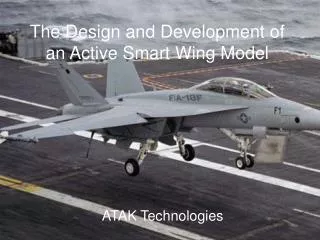
The Design and Development of an Active Smart Wing Model. ATAK Technologies. Team Structure. Thomas Ayers Project Leader Assistant Testing Engineer Robert Aguirre Senior Research Specialist Kevin Mackenzie Senior Modeling and Design Specialist Vu Tran Senior Testing Specialist

E N D
The Design and Development of an Active Smart Wing Model ATAK Technologies
Team Structure • Thomas Ayers Project Leader Assistant Testing Engineer • Robert Aguirre Senior Research Specialist • Kevin Mackenzie Senior Modeling and Design Specialist • Vu Tran Senior Testing Specialist • Dr. R. O. Stearman University of Texas Faculty Consultant
Presentation Overview • Background Information • Aerodynamic Theory • Model Design • Past Group Work • Present Group Work • Summary • Questions
Background Theory Model Work Summary Questions Randall Bolding Wrote a master’s thesis in 1978 in which a wing model was used to research the use of a stabilator as an active control to suppress flutter Lockheed Martin Corporation A research project on the benefits that an active wing can provide in contemporary aircraft design Project Background
Background Theory Model Work Summary Questions At high airspeeds normally latent aerodynamic forces become powerful enough to affect the flow about the airfoil These changes cause torsional moments on the wing Theoretically, the use of active wing control on the leading edge flaps and ailerons can be used in order to better control these latent aerodynamic forces High Airspeed Benefits
Background Theory Model Work Summary Questions At low speeds airflow about the wing can separate from the wing causing a “stall” In natural flight, resonant flapping is used to sustain flight at low flight speeds Theoretically, oscillating the wings by using the control surfaces would create high lift conditions for short, low airspeed maneuvers Low Airspeed Benefits
Aerodynamic Theory • Background Information • Aerodynamic Theory • Model Design • Past Group Work • Present Group Work • Summary • Questions
Aerodynamic Force: Lift • Air flows around the airfoil and create 2 different velocity regions along the top and bottom surfaces of the wing. • velocity increases pressure decreases • Lift is generated due to pressure gradient along the surfaces of the wing. • Background • Theory • Model • Work • Summary • Questions [2]
Lift Coefficient vs. Angle of Attack Lift Analysis = Lift Coefficient Analysis The amount of lift generated by the wings depends on the shape of the airfoil and its inclination with respect to the flow direction. The lift varies almost linearly for small angles of attack (within +/- 10 degrees) [1]. • Background • Theory • Model • Work • Summary • Questions [2] http://www.centennialofflight.gov/essay/Dictionary/angle_of_attack/DI5.htm Feb 2003
Background Theory Model Work Summary Questions Stall occurs when the boundary layer separates from the surface of the wing, causing the lift dramatically decrease. Wing area exposed to the flow increases, thus increasing drag and decreasing velocity. Flow becomes highly unsteady behind the airfoil – turbulence flow. What is Stall? http://wright.nasa.gov/airplane/incline.html Feb 2003
Background Theory Model Work Summary Questions What is Vstall? The velocity of the aircraft when it stalls, which determines the minimum velocity an aircraft can fly. CLmax is the ideal parameter to optimize in order to reduce stall speed How to increase CLmax? - Trailing-edge flaps - Leading edge slats - Oscillating flaps (New)
Background Theory Model Work Summary Questions Flaps change the pressure distribution around the airfoil by changing its chord length and camber, also increase wing area to decrease stall speed. The effect of camber on lift can be explained qualitatively with Newtonian approach and Thin Airfoil Theory. Newtonian approach: Lift is the result of pressure reactions that oppose the turning of flow – higher lift is caused by greater turning Thin Airfoil Theory: Lift-Enhancing Devices [2] http://www.desktopaero.com/appliedaero/airfoils2/highlift.html Feb 2003
Background Theory Model Work Summary Questions Slats – an opening at the leading edge of the airfoil allowing high pressure air under the airfoil to pass. The high pressure air mixes with the air at the top surface and increases the energy of the boundary layer. “By increasing the energy of the boundary layer the wing can sustain higher angles of attack and a higher maximum coefficient of lift” [3] Lift-Enhancing Devices [3]
Background Theory Model Work Summary Questions Oscillating Flap – located near the leading edge of the wing to control the separation of the airflow from the wing – delay the separation or reattach the separated flow onto the surface Vortices are created by oscillating flaps – “enhance the momentum transfer between the free stream and boundary layer, which makes the reattachment of vertices occur more upstream” [3] – the further upstream the vertices are, higher Clmax can be achieved. Moreover, “Clmax is further increased if excitation frequency of flap corresponds to the vortex shedding frequency” [3] Lift-Enhancing Devices
Model Design • Background Information • Aerodynamic Theory • Model Design • Past Group Work • Present Group Work • Summary • Questions
Background Theory Model Work Summary Questions Hydraulic Actuator Electromechanical Actuator Electric Motor Actuator Designs
Background Theory Model Work Summary Questions Available – Dr. Stearman had a hydraulic unit for group use Fast response – Can oscillate at required frequency Powerful – Can easily drive the model control surfaces Hydraulic Actuator System
How do Hydraulics Work? Force that is applied at one point is transmitted to another point using an incompressible fluid. Varying the area of the pistons changes the force output. In this example, the area of the right piston is 9 times greater than the other piston and the force output is thus 9 times the force input. • Background • Theory • Model • Work • Summary • Questions http://science.howstuffworks.com/hydraulic.htm Feb 2003 http://science.howstuffworks.com/hydraulic.htm Feb 2003
Background Theory Model Work Summary Questions Complex – System requires power source, high pressure motor, fluid and tubing Expensive – Available system lacked power source ($500) Size – System is awkward and not easy to set up Maintenance – Pumps, filters need constant up keep Hydraulic System - Drawbacks
Background Theory Model Work Summary Questions Size – Overall system is much smaller Cost – Motor and controller are available from Dr. Stearman for free Maintenance – Does not require any form of maintenance Electromechanical Actuation
Background Theory Model Work Summary Questions A controller drives a motor coupled to a shaft that drives the flaps How does the controller work? [2] [2]
Background Theory Model Work Summary Questions Complexity of controller – Circuit diagram is over 2 pages Size – The controller alone weighs over 35lbs. and would be difficult to mount in the wind tunnel Limited applications – Can only control leading edge flaps Electromechanical Drawbacks [2]
Background Theory Model Work Summary Questions Size of Control System – Electric motor and shaft will be half the size of the previous groups Ease of Operation – Does not require understanding of complex controller Able to Test – By taking wind tunnel dimensions into account when designing we make sure that we will be able to mount the wing in order to obtain Cl and Cd measurements Flexibility – Leading and trailing edge flaps will be able to oscillate. Will be able to control angle of deflection and phase between flaps ATAK Technologies Design [1]
How will our control system work? • Background • Theory • Model • Work • Summary • Questions • Motor mounted to main spar • Shaft drives slider crank assemblies that cause the flaps to oscillate • Hand held tachometer will measure revolutions per minute of the flaps [2] [1]
Project Accomplishments • Background Information • Aerodynamic Theory • Model Design • Past Group Work • Present Group Work • Summary • Questions
Past Accomplishments • Background • Theory • Model • Work • Summary • Questions • Project has been advanced in past three terms • The Active Wing Group (AWG) • Active Wing Technology (AWT) • Active Wing Engineering (AWE)
Background Theory Model Work Summary Questions The Active Wing Group • AWG Work Recovered F-111 wing-tail from storage Investigated limit cycle oscillations Provided a strong foundation for Summer 2002 group • AWG Suggestions Prioritize system hardware recovery
Background Theory Model Work Summary Questions Active Wing Technologies • Research Primarily Research on F-111 Limit cycle oscillations Increasing lift on fighter wings Implementation of control surfaces Digital and analog control systems
Background Theory Model Work Summary Questions AWT Suggestions • Create a mathematical model of control system Create model using either Root Locus or Bode Plot in MatLab • Create digital schematics of all drawings
Background Theory Model Work Summary Questions Active Wing Engineering • Research Aerodynamic Theory behind oscillating flaps • Selected actuation system • Constructed model wing with leading edge flaps
Background Theory Model Work Summary Questions AWE Suggestions • Add leading and trailing edge flaps to new design • Create actuation system to control leading and trailing edge flaps • Select wing type Swept, tapered; Straight, non-tapered • Incorporate Measuring tools for wind tunnel tests
Background Theory Model Work Summary Questions Progress • Research Aerodynamic forces involved in active wing technologies Control surface effect on lift • Model Design Actuation and controller systems • AutoCAD design of wing model • Lab Maintenance Worked to clean WRW 316
Background Theory Model Work Summary Questions Remaining Tasks • Model Design Finalize wing model Construct wing model Incorporate testing system • Perform wind tunnel test Reduce data for analysis
Projected Schedule • Background • Theory • Model • Work • Summary • Questions
Presentation Summary • Background Information • Aerodynamic Theory • Theory Behind the Model and Design Work • Past Group Work • Present Group Work • Future work for ATAK Technologies
References [1] Aguirre, Robert, Thomas Ayers, Kevin Mackenzie, and Vu Tran. “Design and Development of an Active Wing Model.” ATAK Technologies, Austin, TX, Mar. 2003. [2] Garret, Carlos, Justin Gray, and Kevin Marr. “Design of an Active Controlled Wing Model Using Flap Oscillation.” AWE Engineering, Austin, TX, Dec. 2002. [3] Fuentes, David, Basil Philips, and Naoki Sato. “Design and Control Modeling of an Active Variable Geometry Wing.” Active Wing Technologies, Austin, TX, Aug. 2003.