Download
1 / 44
440 likes | 590 Views
The ALICE Inner Tracking System: present and future Vito Manzari – INFN Bari ( vito.manzari@cern.ch ) o n behalf of the ITS Collaboration in the ALICE Experiment at LHC. Outline. ALICE experiment Inner Tracking System Detector overview and Performance ITS Upgrade:

E N D
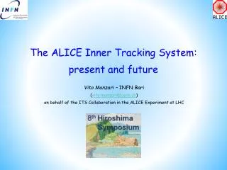
TheALICE Inner Tracking System: present and future Vito Manzari – INFN Bari (vito.manzari@cern.ch) on behalf of the ITS Collaboration in the ALICE Experiment at LHC
Outline • ALICE experiment • Inner Tracking System • Detector overview and Performance • ITS Upgrade: • Physics motivations • Upgrade strategy • R&D activities • Timeline • Conclusions HSTD8 – December7th, 2011
A Large Ion Collider Experiment • ALICE is the dedicated heavy ion experiment at LHC • Study of the behavior of strongly interacting matter under extreme conditions of compression and heat in heavy-ion collisions up to Pb-Pb collisions at 5.5 TeV • Proton-proton collisions: • Reference data for heavy-ion program • Genuine physics (momentum cut-off < 100 MeV/c, excellent PID) HSTD8 – December7th, 2011
The ALICE detector Central Barrel 2 p tracking & PID Dh ≈ ± 1 Detector: Size: 16 x 26 meters Weight: 10,000 tons HSTD8 – December7th, 2011
Central Barrel • Tracking • Pseudo-rapidity coverage |η| < 0.9 • Robust tracking for heavy ion environment • up to 150 points along the tracks • Wide transverse momentum range (100 MeV/c – 100 GeV/c) • Low material budget (13% X0 for ITS+TPC) • PID over a wide momentum range • Combined PID based on several techniques: dE/dx, TOF, transition and Cherenkov radiation • Rate capabilities • Interaction rates: Pb-Pb < 8kHz, p-p < 200 kHz (~30 events in the TPC) • Multiplicities: central Pb-Pb events ~2000, Pb-Pb MB ~ 600 Inner Tracking System (ITS) HSTD8 – December7th, 2011
The Inner Tracking System (ITS) • The ITS plays a key role for the study of yields and spectra of particles containing heavy quarks • The ITStasks: • Secondary vertex reconstruction (c, b decays) with high resolution • Good track impact parameter resolution • < 60 µm (rφ) for pt > 1 GeV/c in Pb-Pb • Improve primary vertex reconstruction, track momentum and angle resolution • Tracking and PID of low pt particles, also in stand-alone • Prompt L0 trigger capability (FAST OR) with a latency <800 ns (SPD) HSTD8 – December7th, 2011
The “current” Inner Tracking System • ITS requirements • Good spatial precision • High efficiency • High granularity (≈ few % occupancy) • Minimize distance of innermost layer from beam axis (mean radius ≈ 3.9 cm) • Limited material budget • Analogue information in 4 layers for particle identification via dE/dx • The ITS (Inner tracking System) consists of 6 concentric barrels of silicon detectors based on 3 different technologies • 2 layers of Silicon Pixel Detector (SPD) • 2 layers of Silicon Drift Detector (SDD) • 2 layers of Silicon double-sided microStrip Detector (SSD) HSTD8 – December7th, 2011
The Inner Tracking System in numbers • Radial distance defined by beam-pipe (inwards) and requirements for track matching with TPC (outwards) • Inner layers: high multiplicity environment (~100 tracks/cm2) 2 layers of pixel detectors HSTD8 – December7th, 2011
PbPb event @ 2.76 A TeV HSTD8 – December7th, 2011
Online SPD Vertex • SPD Vertex built out of tracklets • Same algorithm in pp and PbPb with different configuration parameters • e.g.: cut on # clusters on SPD • Vertex diamond information delivered to LHC • SPD vertex used as input for offline reconstruction HSTD8 – December7th, 2011
Track impact parameter • The transverse impact parameter in the bending plane d0(rφ) is the reference variable to look for secondary tracks from strange, charm and beauty decay vertices • Impact parameter resolution is crucial to reconstruct secondary vertices : below 60 µm for pt > 1 GeV/c • Good agreement data-MC (~10%) Few hundred micron • The material budget mainly affect the performance at low pt (multiple scattering) • The point resolution of each layers drives the asymptotic performance • ITS standalone enables the tracking for very low momentum particles (80-100 MeV/c pions) Pb-Pb HSTD8 – December7th, 2011
Particle IDentification • dE/dx measurement • Analogue read-out of charge deposited in 4 ITS layers (SDD & SSD) • Charge samples corrected for the path length • Truncated mean method applied to account for the long tails in the Landau distribution • PID performance • PID combined with stand-alone tracking allows to identify charged particles below 100 MeV/c • p-K separation up to 1 GeV/c • K- separation up to 450 MeV/c • A resolution of about 10-15% is achieved p-p Pb-Pb p-p HSTD8 – December7th, 2011
Intermediate Summary • The ITS performance are well in agreement with the design values • ALICE has collected p-p and PbPb data at the various energies and the data analysis is progressing very well • Many papers are being published containing very relevant results • Then ….. • Why do wewant to upgrade the ITS? HSTD8 – December7th, 2011
ITS Upgrade Motivations • Extend ALICE capability to study heavy quarks as probes of the QGP in heavy-ion collisions • Main Physics Topics and Measurements of interest • Study the quark mass dependence of the energy loss • Measure the Nuclear Modification factor RAAvspT, down to low pT, of D and B mesons • Study the thermalization process of heavy quarks in the hot and dense medium formed by heavy ion collisions • Measure the baryon over meson ratio (Λc / D or Λb/ B) • Measure elliptic flow of charged mesons • Exploit the LHC luminosity increase improving the readout capabilities, now limited to ≈1 kHz HSTD8 – December7th, 2011
Upgrade Strategy • Improve the impact parameter resolution by a factor 2÷3 • How: • Reduce of the radial distance of the innermost layer (closest to the IP) • Reduce of the material budget • Reduce of the pixel size • Physics reach: • Low pT heavy-flavour mesons • v2 of charmed hadrons • Heavy flavour baryons (Λc,Λb, …) • Better identification of secondary vertices from decaying charm and beauty and increase statistical accuracy of channels already measured by ALICE (e.g. displaced D0, J/Ψ, etc.) HSTD8 – December7th, 2011
Upgrade Strategy • Improve trigger capabilities • How: • Improve standalone tracking efficiency and pT resolution • Selection of event topologies with displaced vertices at Level 2 (~100 μs) • Physics reach: • Strong enhancement of relevant signals • Exploit luminosity increase • How: • Improve readout time and standalone tracking capability • Physics reach: • Strong enhancement of relevant signals HSTD8 – December7th, 2011
Improve the impact parameter resolution • Get closer to the IP • Radius of innermost Pixel layer is defined by central beam pipe radius • Present beam pipe: ROUT = 29.8 mm, ΔR = 0.8 mm • New Reduced beam pipe: ROUT = 19 mm, ΔR = 0.5 mm • Reduce material budget (especially innermost layers) • reduce mass of silicon, electrical bus (power and signals), cooling, mechanics • Present ITS Pixel layers: X/X0 ~1.14% per layer • Target value for new ITS: X/X0 ~0.3 – 0.5% per layer • Reduce pixel size • Reduce size of interconnect bumps, monolithic Pixels • currently 50μm x 425μm HSTD8 – December7th, 2011
Improve tracking, triggeringandpTresolution • Higher standalone tracking efficiency • Increase granularity • Increase number of layers in the outer region (seeding) and inner region (occupancy) • Extended trigger capabilities • High standalone tracking efficiency • Low readout time < 50μs for Pb-Pb, ~μs for p-p (current ITS ~1ms in both cases) • Increase momentum resolution • increase track length • increase spatial resolution • reduce material budget HSTD8 – December7th, 2011
Upgrade Scenario • 7 silicon layers (r = 2.2÷ 45 cm) or more to cover the region from IP to TPC • 3innermost layers made of pixels, 3 outer layers either pixels or double sided strips • Pixel size ~ 20-30 µm (rφ), rφresolution ~ 4÷ 6 µm • Material budget 0.3 ÷ 0.5% X0per layer • Power consumption 250-300 mW/cm2 • Innermost pixel layer: ultra-light high-resolution high-granularity as-close-as-possible to IP (r ≈ 2.2 cm) • Hit density ~ 100 tracks/cm2 in HI collisions • Radiation tolerant design (innermost layer) compatible with 2 Mrad / 2 x10¹³neq over 10 years (safety factor ~2 included) HSTD8 – December7th, 2011
Upgrade Scenario • The new ITS will be based on Pixel and Strip detectors • The innermost layers should be mounted on an insertable mechanics and should be served from one side only for a fast replacement in case of reduced efficiency Current Upgrade HSTD8 – December7th, 2011
Impact parameter resolution • An additional innermost pixel layer would achieve already a substantial improvement of the pointing resolution (factor 3 at 200 MeV/c) ITS standalone tracking • However, a completely new ITS is mandatory to improve the standalone tracking efficiency at low pT and cope with the increased LHC luminosity • New detector technologies for a faster readout HSTD8 – December7th, 2011
Standalone Tracking Efficiency • A factor 2 gain in tracking efficiency at 200 MeV is achieved with the configuration under study • Tracking efficiency and an improved d0 resolution allow to detect charmed and beauty hadrons below 2 GeV/c HSTD8 – December7th, 2011
Physics signal benchmark D0 Kπ Increase of the statistical significance reduction the statistical uncertainty! pT range not accessible with the current ITS HSTD8 – December7th, 2011
Physics signal benchmark Λc New measurement! Important physics reach: barion over meson ratio in heavy-quark sector HSTD8 – December7th, 2011
R&D activities • Pixel detectors • Hybrid pixels with reduced material budget and small pitch • Monolithic pixels rad-tolerant • Double-sided strip detectors (outer layers) • Shorter strips and new readout electronics • Electrical bus for power and signal distribution • Low material budget • Cooling system options • air cooling, carbon foam, polyimide and silicon micro-channels structure, liquid vs evaporative • low material budget HSTD8 – December7th, 2011
Monolithic Pixel R&D • State-of-the-art architecture (MIMOSA family) uses rolling-shutter readout • Pixel size ~20 µm possible • Target for material budget < 0.3 % X0(50 µm thick chip) • STAR HFT Monolithic: 0.37% X0 • Ongoing developments: • Evaluation of properties of a quadruple well 0.18 CMOS • radiation tests structures • study characteristics of process using the MIMOSA architecture as reference • design of new circuit dedicated to ALICE (MISTRAL) • investigation of in-pixel signal processing using the quadruple-well approach • Novel high resistivity base material for depleted operation (LePix) HSTD8 – December7th, 2011
Hybrid Pixel R&D • Pixel size limit due to flip chip bonding technology (~30 µm) • Target for overall material budget < 0.5 % X0, about 1/3 of silicon • (100 µm sensor, 50 µm front-end chip) • Present SPD 1.14% X0, silicon 0.38% X0 • (200 µm sensor, 150 µm front-end chip) • Edgeless sensors to reduce insensitive overlap regions • High S/N ratio, ~ 8000 e-h pairs/MIP • Power/Speed optimization • Proven radiation hardness • Ongoing developments: • Thin and Edgless detectors (FBK, VTT, IZM) • Low cost bump bonding, Lower power FEE HSTD8 – December7th, 2011
Double-sided Micro-strip R&D • Sensor layout • Strip detector technologies are rather mature • Optimize the design to cope the expected higher multiplicity at smaller radius and nominal LHC energy • Optimize stereo angle to limit ambiguities in track reconstruction • Smaller “virtual” cell to reduce occupancy • Front-end electronics • Low-momentum PID requires a wide dynamic range • Data digitization directly on front-end chip • Ongoing developments • Sensor layout • Fully differential front-end chip • ADC or ToT for the digitization of the analogue information HSTD8 – December7th, 2011
ITS Upgrade Timeline • The upgrade should target the 2017-18 shutdown (Phase I) • Decisions on the upgrade plans in terms of physics strategy, detector feasibility and funding availabilitywill be taken in 2012 • The global upgrade may require a two-stage approach with a Phase II in 2020 and beyond. • end 2011: Preparation of a Conceptual Design Report • 2011-2014: R&D for Phase I • 2014-2016: Production and pre-commissioning for Phase I • 2017-2018: Installation and commissioning for Phase I HSTD8 – December7th, 2011
Conclusions • The current Inner Tracking System performance is well in agreement with the design requirements and expectations • The achieved impact parameter resolution allows to reconstruct the secondary vertices of charm decays • Standalone capability allows to track and identify charged particles with momenta down to 100 MeV/c • An upgraded ITS will extend the ALICE physics capabilities: • Strong increase of the statistical accuracy in the measurements of yields and spectra of charmed mesons and baryons already possible with the present detector • Asignificant extension of the present physics programmewith new measurements that at present are not possible • Several options for the detector technology implementation are being investigated and developed HSTD8 – December7th, 2011
Back-up slides HSTD8 – December7th, 2011
“Russian Doll” Installation SDD barrel SSD barrel • Inserting the SDD barrel inside • the SSD barrel HSTD8 – December7th, 2011
“Russian Doll” Installation SPD half-barrels mounted face to face around the beam pipe • Moving of the SDD+SSD barrel • over the SPD HSTD8 – December7th, 2011
“Russian Doll” Installation • Moving the TPC over the ITS barrel, i.e. SPD+SDD+SSD HSTD8 – December7th, 2011
SPD L0 trigger SPD Half Stave Readout MCM Half stave 141 mm Sensor 1 Sensor • Overall latency constrain 800 ns (Central Trigger Processor) • Key timing processes are data deserialization and Fast-OR extraction • Algorithm processing time < 25 ns • 10 Algorithms provided in parallel • Detectors commissioning, p-p and PbPb physics • Cosmic, minimum bias and multiplicity algorithms Pixel chips • The SPD is made of 120 modules, called half-staves • Pixel chip prompt Fast-OR • Active if at least one pixel hit in the chip matrix • 10 signals in each half-stave (1200 signals in total) • Transmitted every 100 ns HSTD8 – December7th, 2011
Tracking strategies • “Global” • Seeds in outer part of TPC (lower track density) • Inward tracking from the outer to the inner TPC radius • Matching the outer SSD layer and tracking in the ITS • Outward tracking from ITS to outer detectors PID ok • Inward refitting to ITS Track parameters OK • “ITS stand-alone” • Recovers not-used hits in the ITS layers • Aim: track and identify particles missed by TPC due to pt cut-off, dead zones between sectors, decays • pt resolution ≤ 6% for a pion in pt range 200-800 MeV/c • pt acceptance extended down to 80-100 MeV/c (for ) TPC-ITS track matching pt resolution HSTD8 – December7th, 2011
Vertexing • Primary vertex reconstructed with tracklets • Tracks reconstruction starts from outside (TPC) towards ITS using the vertex as seed • TPC reconstructed tracks are matched with SSD outer layer • Once the reconstruction reaches the first SPD layer it is back-propagated • Re-fit from outside and the vertex is recalculated using the tracks HSTD8 – December7th, 2011
Upgrade Simulation Tools • 3 independentsimulationtoolshavebeendeveloped • Fast EstimationTool: “Toy-Model” originallydeveloped by the STAR HFT collaborationwhichallows to build a simple detector model. The model featured the calculation of the covariancematrixateachstep of a measurement (e.g. layer with radiusr) including the multiple scattering. • Fast MC Tool: Extension of the FET thatallowsto disentangle the performance of the layout from the efficiency of the specictrackfindingalgorithm. • Full MC: Transport code (geant3) designed to be flexible : the detector segmentation, the number of layers, theirradii and materialbudgets can be set asexternalparameters of the simulation. HSTD8 – December7th, 2011
Upgrade Simulation Validation Fast Estimation Tool (pions) Full MC • Fast MC shows the sameperfomanceas the FET • The 3 simulationtoolsreproduce the current ITS performance HSTD8 – December7th, 2011
Pointing Resolution • Effects of the innermost layer L0 • No vertex resolution Radial Distance Material Budget HSTD8 – December7th, 2011
Pointing Resolution Spatial Resolution • Configuration design for betterpointingresolutionperformances: • ImprovementatlowpT: • Smallestradialdistance to the beam line • Smallestmaterialbudget • Improvementat high pT: • Smallestcellsize HSTD8 – December7th, 2011
Particle Identification • Different configurations are being studied Red : proton/Kaonseparation Black : kaon / pionseparation HSTD8 – December7th, 2011
Hybrid pixel material budget • Each urrent SPD layer • Carbon fiber support: 200 μm • Cooling tube (Phynox): 40 μmwall thickness • Grounding foil (Al-Kapton): 75 μm • Pixel chip (Silicon): 150 μm 0.16% • Bump bonds (Pb-Sn): diameter ~15-20 μm • Silicon sensor: 200 μm 0.22% • Pixel bus (Al+Kapton): 280 μm 0.48% • SMD components • Glue (Eccobond 45) and thermal grease Two main contributors: siliconand interconnect structure (bus) HSTD8 – December7th, 2011
How material budget can be reduced • How can the material budget be reduced? • Reduce silicon chip thickness • Reduce silicon sensor thickness • Thin monolithic structures • Reduce bus contribution (reduce power) • Reduce edge regions on sensor • Review also other components (but average contribution 0.1-0.2%) • What can be a reasonable target • Hybrid pixels: ~0.5%X0 • silicon: 0.16% X0(present SPD 0.38%) • bus: 0.24% X0(present SPD 0.48%) • others: 0.12%X0 (present SPD 0.24%) • Monolithic pixels: 0.37% X0(as for STAR HFT) HSTD8 – December7th, 2011