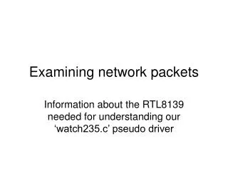
Analyzing Network Packets
SWE 344 Internet Protocols & Client Server Programming. Analyzing Network Packets. Network Packets . The network packets (that we capture) contain several layers of information to help the data get transported between the two network devices.


Analyzing Network Packets
E N D
Presentation Transcript
SWE 344 Internet Protocols & Client Server Programming Analyzing Network Packets
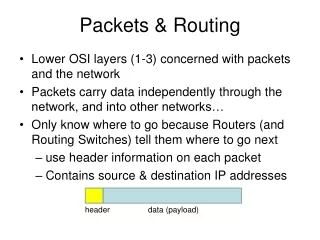
Network Packets • The network packets (that we capture) contain several layers of information to help the data get transported between the two network devices. • Each layer of information contains bytes arranged in a predetermined order, specifying parameters specific for the protocol layer. • Most packets that we will use in IP network programming will contain three separate protocol layers of information, along with the actual data being transmitted between network devices.
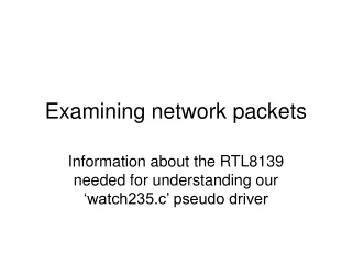
The Ethernet Layer • The first layer of the network packet is called the Ethernet header. • Three types of Ethernet protocol packets on our network: Ethernet 802.2, Ethernet 802.3, and Ethernet version 2. • The Ethernet 802.2 and 802.3 protocols are IEEE standard protocols defined for Ethernet layer traffic. Ethernet version 2 is a legacy protocol that is not a standard protocol per se, but it is the most common protocol used on Ethernet networks. • Almost all devices (including Windows systems) use the Ethernet version 2 protocol to transmit IP packets by default.
The Ethernet Layer • The Ethernet version 2 header shows the Media Access Card (MAC) addresses that are used to identify individual devices on the Ethernet network, along with an Ethernet protocol number that identifies the next layer protocol contained in the Ethernet packet. Each Ethernet packet conforms to a predetermined layout: • A 6-byte destination Ethernet (or MAC) address • A 6-byte source Ethernet (or MAC) address • A 2-byte next-layer protocol identifier • A data payload of 46 to 1500 bytes • A 4-byte checksum • The data payload must contain a minimum of 46 bytes to ensure that the Ethernet packet is at least 64 bytes long. (This helps prevent collisions, because sending shorter packets could cause a collision on the network) • The checksum value supplies a rudimentary error checking mechanism for the data on the network. If the packet becomes corrupt in transit, the checksum will not compute properly, and the packet is marked as bad.
Ethernet Address • The Ethernet addresses of devices are assigned by the network card vendor and should not be changed (even though in some instances software allows you to override that address). • Each device on an Ethernet network must have a unique MAC address. The MAC address consists of two parts: • A 3-byte vendor identifier, or Organizationally Unique Identifier (OUI) • A 3-byte device serial number unique to the vendor • The resulting 6-byte network address uniquely identifies the network card on the network, no matter how large the network is. • The Internet Assigned Numbers Authority (IANA) assigns vendors MAC addresses to ensure there is no duplication. • The assigned numbers are published in Internet Request For Comments (RFC) documents (the most recent Assigned Numbers RFC is RFC 1700). The IANA also maintains a web page (www.iana.org) that contains the most current Ethernet vendor information.
Ethernet Address • After the 3-byte vendor portion, a 3-byte unique serial number is added to produce the unique 6-byte address. • You may see Ethernet addresses referenced in several ways; here are some of the traditional formats: • As a single value: 0020AFBCCEC3 • Using colons: 00:20:AF:BC:CE:C3 • Using hyphens: 00-20-AF-BC-CE-C3
Ethernet Protocol Type • The other important part of the Ethernet header is the Protocol Type field. • The difference between the Ethernet version 2 packet and the Ethernet 802.2 and 802.3 packets occurs in the Protocol Type field. • The 802.2 and 802.3 packets both contain a 2-byte value in the same location of the packet, and they both use the value to indicate the total size of the Ethernet packet. • The Ethernet version 2 protocol uses those same 2 bytes to define the protocol type used in the next level packet that is contained within the Ethernet packet
The IP Layer The next protocol layer in the Analyzer capture packet is the IP packet. The packet details frame shows the IP layer section of the Analyzer capture for a specific packet. As you can see, the IP protocol defines several additional fields of to the Ethernet protocol information.
Table below describes the IP fields found in the Analyzer capture
The value of each field can be seen in the Analyzer packet details frame. Fields that contain more than one type of information, such as the Type of Service and Flags fields, can be expanded to show all of the values in the field. The following sections describe some of the more important fields of the IP packet that you might have to watch for in your traces.
Address Fields While Ethernet addresses are good for uniquely identifying devices on a LAN, they do not help at all for identifying remote devices. It is impossible to look at an Ethernet address and determine what network it is on. To help uniquely identify the devices on separate networks, the IP addressing scheme uses particular bits of the 32-bit address to identify address features. The IP address is divided into three parts: A preset number of high bits used to identify the packet address scheme used A predetermined network address A device address on the network From 1 to 4 high bitsidentify how the network and device addresses are determined within the total 32 bits of the IP address. The network address identifies the unique network where the device is located. Every network should have a unique IP network address assigned to it. IP routers can use the network address information to decide the routing of individual IP packets to the proper remote network, even when they are located across the Internet. The device address uniquely identifies the device within the network address. No two devices with the same network address can have the same device address. By default the IP address specification uses the 4 high bits to define four classes of network addresses, as shown in the following table:
The 32-bit IP address is almost always broken down into four 8-bit (1 byte) segments, which can then be represented by decimal numbers with periods between them, called dotted decimal notation. This is the IP address format you are likely most used to seeing. The decimal numbers are ordered with the network address part on the left side and the host part on the right side. Using the dotted decimal notation of the IP address, the network class ranges become as follows:
To complicate things even more, individual class networks can be further divided into other networks, or subnets. Each subnet must use a common network address scheme to identify it among the other subnets in the class network. To identify the network part of the IP address, a subnet maskis defined for a particular subnet. The subnet mask identifies the bits of the IP address that are used to define the network address part, and the bits used to define the host address.
Example By default, a class B network address would have a subnet mask of 255.255.0.0, indicating that the upper 16 bits (or first two decimal numbers) are devoted to the network address. The lower 16 bits (or second two decimal numbers) are used to define individual host addresses on the network. Thus, in a default class B network, hosts 130.100.1.6 and 130.100.10.5 are on the same network. Using subnets, however, you can add extra bits to the network address to create subnets of the class B network. For example, if the class B network address 130.100. uses a subnet mask of 255.255.255.0, the third octet also becomes part of the network portion of the address. Thus the individual subnets become 130.100.x.0, where x can be anything from 0 to 255. This causes address 130.100.1.6 to be a separate network from address 130.100.10.5 because the third octets are different. The hosts on the subnet network can have addresses ranging from 130.100.x.1 to 130 .100.x.254 (the host address of all 1s, 192.168.x.255, is reserved as a subnet broadcast address). This allows for a single class B address to contain up to 256 subnets, all supporting different networks. This technique is used most often for large building LANs as well as campus LANs to help divide the total number of devices on a network to a manageable number.
Fragmentation Flags • One of the many complexities of IP packets is their size. The maximum size of an IP packet can be 65,536 bytes. This is a huge amount of data for an individual packet. In fact, most lower-level transports (such as Ethernet) cannot support carrying a large IP packet in one piece (remember, the Ethernet data section can only be 1,500 bytes long). To compensate for this, IP packets employ fragmentation to divide the IP packet into smaller parts for transport to the destination. When the pieces arrive at the destination, the receiving software must have a way to recognize the fragmented packet and reassemble the pieces back into a single IP packet. • Fragmentation is accomplished using three fields of the IP packet, the fragmentation flags, the fragment offset, and the identification fields. The fragmentation flags consist of three 1-bit flags: • A reserved flag, which must be zero • A Don’t Fragment flag, which indicates that the IP packet may not be fragmented • A More Fragment flag, which indicates that this packet is an IP fragment and more fragments are on the way • The IP Identification field uniquely identifies each IP packet. All the fragments of any packet will have the same identification number. This tells the receiving software which packets need to be joined together to create the original IP packet. The fragment offset field indicates the location for the fragment in the original packet.
Type of Service Field • The Type of Service field identifies a Quality of Service (QoS) type for the IP packet, to mark an individual IP packet (or a stream of IP packets) as having a particular priority. In the past this field was not used much. However, recently there has been a push for using this field to prioritize real-time data such as video and audio streams. This will help routers and other network devices to give real-time data packets a higher priority of service to reduce the delay in their transmission. In most network traffic, the Type of Service field will be set to all zeros, indicating normal, routine data. However, with the increased use of IP for transporting real-time data, you may encounter applications that use the Type of Service field to prioritize packets. • The Type of Service (ToS) field contains 8 bits of information, divided into the following subfields: • 3 bits used as a precedence field • 1 bit used to denote normal or low delay • 1 bit used for normal or high throughput • 1 bit used for normal or high reliability • 2 bits reserved for future use
Programming with TCP and UDP TCP Programming Features The most important thing to remember about using TCP is that it is a connection-oriented protocol. Once a connection exists between two devices, a reliable data stream is established to ensure that data is accurately moved from one device to the other. Although with TCP your applications do not need to worry about lost or out-of-order data, there is one huge consideration when you are programming with TCP: the buffers. Because TCP must ensure the integrity of the data, it keeps all sent data in a local buffer until a positive acknowledgement of reception is received from the remote device. Similarly, when receiving data from the network, TCP must keep a local buffer of received data to ensure that all of the pieces are received in order before passing the data to the application program. Because of the separate TCP buffer, data moving between your program and the destination program on the remote host is handled somewhat differently than what you might expect.
The TCP subsystem on the Windows OS is responsible for accepting data from your application and the incoming data from the remote device. Instead of being immediately sent out on the network, the data will sit in the buffer for a set amount of time. In the meantime, your application may send more data to the remote host, which in turn will also be added to the buffer (as shown by the data1 and data2 data packets). When the TCP subsystem is ready to send the data to the remote device, it will attempt to send all of the contents of the buffer, not just individual pieces, so both the data1 and data2 buffers are sent as a single packet. The receiving host then receives a single packet of data, comprising both the data1 and data2 buffers. It is up to the application program to determine if this is really two separate chunks of data or one large chunk of data.
What does this mean to you as a network programmer? When you send data in messages to a remote device, the remote device won’t necessarily receive the data in the same number of message units. The TCP subsystem will place all of the individual messages of data into the TCP buffer. Depending on the rate at which you are sending data and the rate at which the receiving device is receiving data, those messages (or at least some of them) may get pushed together in the data stream. This “feature” of TCP communications surprises many a novice network programmer. Because TCP does not preserve data message boundaries, you must compensate for that in your network programs. There are two ways to handle this: Create a protocol that requires a one-for-one response to each data message sent from the host Design a data message marker system to distinguish data message boundaries within the data stream Both techniques require a fair amount of forethought before coding begins. Most Internet protocols that use TCP implement the first way of separating data. FTP and similar protocols implement a command/response system where the client sends one message command at a time and waits for the response for each command from the remote host.
UDP Programming Features UDP was created to solve the message boundary problem of TCP. UDP preserves data boundaries of all messages sent from an application to the network. Because UDP was specifically designed not to worry about reliable data transport, it does not need to use local buffers to keep sent or received data. Instead, each message is forwarded as a single packet as it is received from the application program. Also, each message received from the network is forwarded to the application program as a single message. UDP preserves the message boundary in the network packet.
Apart from UDP’s capability to preserve message boundaries, it has another problem. Because UDP does not guarantee data delivery, your application must perform that function if it is concerned about the data getting to its destination. Just because a device sends a UDP data packet doesn’t necessarily mean that the receiving device received it. You must ensure that your program can deal with missing data packets. One way around this is to always expect some type of answer from the remote host after you send out a data packet (the command/response method). When no answer is received, you should assume that your data packet did not make it through the network to the remote device. This makes sending data via UDP a four-step process: Send data to the remote device. Start a timer, set for a predetermined period of time. Wait for a response from the remote device. When it arrives, stop the timer and go on with your program. If the timer expires before you receive a response, go back and repeat step 1. After you have repeated step 1 a set number of times (the retry count) without an answer, assume that you cannot communicate with the remote host. Although sending data using UDP is somewhat easier as far as message boundaries go, it is a lot more complicated than TCP because you need to do your own checking for lost data packets.
Finding IP Address Information One of the biggest challenges of network programming is dealing with network configurations of individual workstations and servers. When sending data across the network, you often need to determine the IP network information for the system running your program. The Windows OS family offers many ways to determine IP configuration information, both manually and from within a program. This section demonstrates a few of the ways that you can use to determine IP configuration information both manually and within your C# programs. Using ipconfig C:\>ipconfig Windows NT IP Configuration Ethernet adapter El90x1: IP Address. . . . . . . . . : 192.168.1.6 Subnet Mask . . . . . . . . : 255.255.255.0 Default Gateway . . . . . . : 192.168.1.1 PPP adapter NdisWan5: IP Address. . . . . . . . . : 0.0.0.0 Subnet Mask . . . . . . . . : 0.0.0.0 Default Gateway . . . . . . : C:\>
To obtain more detailed information about a device, use the /all switch for the ipconfig command, as shown here: Description . . . . . . . . : 3Com EtherLink PCI Physical Address. . . . . . : 00-50-DA-10-78-67 DHCP Enabled. . . . . . . . : No IP Address. . . . . . . . . : 192.168.1.6 Subnet Mask . . . . . . . . : 255.255.255.0 Default Gateway . . . . . . : 192.168.1.1 PPP adapter NdisWan5: Description . . . . . . . . : NdisWan Adapter Physical Address. . . . . . : 00-00-00-00-00-00 DHCP Enabled. . . . . . . . : No IP Address. . . . . . . . . : 0.0.0.0 Subnet Mask . . . . . . . . : 0.0.0.0 Default Gateway . . . . . . : C:\>ipconfig /all Windows NT IP Configuration Host Name . . . . . . . . . : shadrach.blum.lan DNS Servers . . . . . . . . : 192.168.1.1 192.168.1.2 192.168.1.3 Node Type . . . . . . . . . : Broadcast NetBIOS Scope ID. . . . . . : IP Routing Enabled. . . . . : No WINS Proxy Enabled. . . . . : No NetBIOS Resolution Uses DNS : No Ethernet adapter El90x1:
Using the Registry • IP Info in the Registry • The Registry consists of individual keys that store one or more data items. Each key stores information for an entity on the system, such as a network card. Each data item has a value that defines the data information. The Registry key organization is similar to a directory/ subdirectory structure. A key may contain data as well as several subkeys. Each subkey itself may contain data and additional subkeys; the structure can go several levels deep. • The Windows Registry comprises six base keys from which all other keys are built: • CLASSES ROOT • CURRENT CONFIG • CURRENT USER • DYN DATA • LOCAL MACHINE • USERS
Within this subkey, the information for each network interface is stored as a separate subkey, named sequentially starting with 0000. Each subkey contains data values that define the IP information for an individual network device Network Information Registry Data Names
looking for network information on a Windows NT, 2000, or XP system The first step is to find the Registry keys of all the network devices configured on the system. Windows NT, 2000, and XP systems have a single Registry key that lists all network interfaces configured on the system. This key is listed under the HKEY_LOCAL_MACHINE (HKLM) root key. The actual subkey is as follows: HKLM\Software\Micrososft\Windows NT\CurrentVersion\NetworkCards
Using C# to Search the Registry • Microsoft.Win32.Registry The Microsoft.Win32.Registry namespace contains all the base classes needed to access the base Registry key names: • Current_User, • Local_Machine, • Classes_Root, • Current_Config, • Dyn_Data, and Users. • You must use one of the base Registry key names to build your specific Registry subkey. • Microsoft.Win32.RegistryKey The Microsoft.Win32.RegistryKey namespace contains the classes and methods necessary to query and modify Registry keys and data. The OpenSubKey() method allows you to open a subkey of a known key and access any data values contained in the subkey. Once you have the appropriate subkey, you can use the GetValue() method to get the data values assigned to the subkey.
Example The following program will find the network devices installed on a Windows NT, 2000, or XP system using the system Registry, and display the IP information for each device. using System; using Microsoft.Win32; class CardGrab { public static void Main () { RegistryKey start = Registry.LocalMachine; RegistryKeycardServiceName, networkKey; string networkcardKey = "SOFTWARE\\Microsoft\\ WindowsNT\\CurrentVersion\\NetworkCards"; string serviceKey = "SYSTEM\\CurrentControlSet\\Services\\"; string networkcardKeyName, deviceName; string deviceServiceName, serviceName; RegistryKeyserviceNames = start.OpenSubKey(networkcardKey); if (serviceNames == null) { Console.WriteLine("Bad registry key"); return; }
deviceServiceName=(string)cardServiceName.GetValue("ServiceName");deviceServiceName=(string)cardServiceName.GetValue("ServiceName"); deviceName = (string)cardServiceName.GetValue("Description"); Console.WriteLine("\nNetwork card: {0}", deviceName); serviceName = serviceKey + deviceServiceName + "\\Parameters\\Tcpip"; networkKey = start.OpenSubKey(serviceName); if (networkKey == null) { Console.WriteLine(" No IP configuration set"); } else { string[] ipaddresses = (string[])networkKey.GetValue("IPAddress"); string[] defaultGateways = (string[])networkKey.GetValue("DefaultGateway"); string[] subnetmasks = (string[])networkKey.GetValue("SubnetMask"); foreach(string ipaddress in ipaddresses) { Console.WriteLine(" IP Address: {0}",ipaddress); } foreach(string subnetmask in subnetmasks) { Console.WriteLine(" Subnet Mask: {0}", subnetmask); } foreach(string defaultGateway in defaultGateways) { Console.WriteLine(" Gateway: {0}", defaultGateway); } networkKey.Close(); } } start.Close(); } }