
Enhancing Settling Time in Uncooled IR Detectors Through PID Control**
E N D
Presentation Transcript
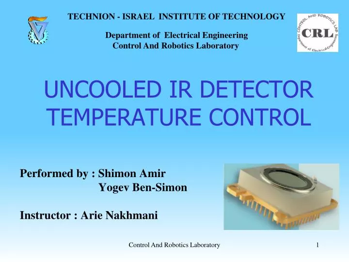
TECHNION - ISRAEL INSTITUTE OF TECHNOLOGYDepartment of Electrical Engineering Control And Robotics Laboratory UNCOOLED IR DETECTORTEMPERATURE CONTROL Performed by : Shimon Amir Yogev Ben-Simon Instructor : ArieNakhmani Control And Robotics Laboratory
OUTLINE PRESENTATION PROBLEM SYSTEM STRUCTURE PROJECT GOALS & OPTIONAL SOLUTIONS CHOSEN SOLUTION RESULTS FINDINGS SUMMARY CONCLUSIONS Control And Robotics Laboratory
PROBLEM Detector “BIRD 384” is IR detector type uncooled . This kind of detector requires stable substrate temperature . The requirement for temperature deviation is +/- 10mK . During the characterization after manufacture the detectors pass series of tests ,which include settling to several set points. This procedure takes a lot of time , therefore we need to reduce the detector settling time. The initial tests showed that there is variance between the time response of the detectors . Control And Robotics Laboratory
SYSTEM STRUCTURE Detector Controller & Acquisition Mechanical Stand active element: TEC Microcontroller embedded on FPGA Heat sink Measurement : RTD PT100 Thermal Coupling 24 bit ADC 20 bit DAC linear power amplifier Control And Robotics Laboratory
Uncooled IR Detector Alumina RTD TEC Control And Robotics Laboratory
Thermoelectric Cooler (TEC) Control And Robotics Laboratory
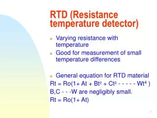
PT100 RTD Platinum RTDs ( Resistance Temperature Detectors ) are recognized as the most reliable standard available for temperature measurement . The PT100 RTD is described by the following generic equation , which makes a obvious nonlinear relationship between temperature and resistance: Since the B and C coefficients are relatively small, the resistance changes almost linearly with the temperature. Control And Robotics Laboratory
Mechanical Stand Gap Filler For Thermal coupling Electronic card & Detector Control And Robotics Laboratory
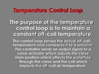
Control loop Control And Robotics Laboratory
PROJECT GOALS & OPTIONAL SOLUTIONS The project goals : • To reduce settling time . • To improve the robustness . • Identify the reasons for the variance between the settling time of detectors . Optional solutions : • To improve the control algorithm . • To improve the physical parameters of the system/detector such as : • Thermal impedance between detector package and the heat sink. • Heat sink. • “Inside of the package”, e.g. internal PT100 sensor location. Control And Robotics Laboratory
CHOSEN SOLUTION System modeling . Algorithm : PID + switch mode - full power until getting to set-point area ,initializing the integral with a desired value , and then continue with closed loop to convention. PID tuning using software tool and manual adjustment. Mechanics : improve the thermal coupling to the heat sink. Control And Robotics Laboratory
System Modeling • The chosen model is second order system : one pole for the TEC and another one for the temperature sensor. • Even though we know that there is delay in thermal system , in our system the delay can be neglected. • Initial system modeling using step response of the open loop system , and set the system parameters using software tool . Temperature [ oC ] Time [ sec ] Control And Robotics Laboratory
Plant Simulink Model Control And Robotics Laboratory
Modeling Results The results for the second order estimation : DET 1(OK) : DET 2 (SLOW): HIGH VARIANCE Control And Robotics Laboratory 14
PID tuning using sisotool Control And Robotics Laboratory
RESULTS • The results of the PID tuning using sisotool : • P = 15 • I = 0.008 • and after manual adjustment : • P = 7 • I = 0.02 Control And Robotics Laboratory
SETTLING TIME RESULTS Measurements were taken from 8 detectors that tested in 3 configurations : • Original system - “Old”. • Improved controller and manually PID tuning – “New” • Improved controller , heat sink and thermal impedance - “New +Pad” Control And Robotics Laboratory
IMPROVEMENTS Control And Robotics Laboratory
Comparison Between Detector #1 Results For The Jump 25 60 Det 1 “Old” Det 1 “New+Pad” Det 1 “New” fig. 1 : Det 1 “old” settling time to +/-10mK fig. 3 : Det 1 “New” settling time to +/-10mK fig. 5 : Det 1 “New+Pad” settling time to +/-10mK fig. 2 : zoom on the relevant area in fig. 1 fig. 4 : zoom on the relevant area in fig. 3 fig. 6 : zoom on the relevant area in fig. 5
MEASUREMENT QUALITY Temperature sense readout circuits accuracy and quality is very important. Testing the accuracy and noise of the temperature sense circuits was done by replacing the RTD with a regular resistor of 118.2 ohm [~ 46.5 deg’]. Readout circuits noise is ~10mK pk-pk. Impact of readout circuits temperature drift is less then 20mK for 10 deg’ change of surroundings. ~10mK Control And Robotics Laboratory 20
FINDINGS • There are two main kinds of temperature stability problems: • “Detector slow response” • “Detector can’t cool down” • Slow response : the problem is mainly TEC-alumina and alumina-RTD contacts. • Not cooling : the problem is mainly TEC-package contact. Control And Robotics Laboratory
RTD ASSEMBLY Control And Robotics Laboratory 22
GLUINGS TEC - PACKAGE ALUMINA-TEC RTD SURFACE Control And Robotics Laboratory 23
MECHANICS • The current design includes a gap filler pad as thermal coupling to the heat sink . • It has a thermal conductivity of 2 . and with 2mm thickness it’s thermal impedance is 1.3 . • Compression achieved using material elasticity and socket friction . • Possible improvement can be achieved by using a thermal pad with a better thermal impedance and a copper heat sink. – will require mechanical adjustments. • Tested – 0.3 mm thermal pad with aluminum film to avoid pull-out (pad stick to the detector’s package) effect, thermal conductivity of 17 and thermal resistance of 0.06 , copper heat sink . Control And Robotics Laboratory
SUMMARY • Settling time improvement of 30%-40% has been achieved. • Reasons for variance has been identified . • Manufacturing process is being modified . Control And Robotics Laboratory
CONCLUSIONS Points of view for future work : • To build a better model , linear or non-linear ,and check the influence of adding derivative . • To explore robust control methods . • To explore adaptive control methods . • Check the influence of adding derivative . • Change the location of the temperature sensor. • Thermal coupling improvement. • Thermal mass reduction. • Better heat sink. Control And Robotics Laboratory