Download

1 / 16
180 likes | 436 Views
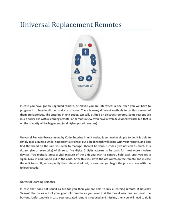
Project Title. USING TV REMOTE AS A CORDLESS MOUSE FOR THE COMPUTER Under the Guidance of Submitted by. ABSTRACT. A typical TV remote sends coded infrared data that is read by an IR sensor duly interfaced to a microcontroller and then to the com port of a PC.

E N D
Project Title USING TV REMOTE AS A CORDLESS MOUSE FOR THE COMPUTER Under the Guidance of Submitted by
ABSTRACT • A typical TV remote sends coded infrared data that is read by an IR sensor duly interfaced to a microcontroller and then to the com port of a PC. • This IR code is traditionally RC5 code as followed by remotes from PHILIPS. • The same data is then burnt to a microcontroller the output of which shall drive desired operation through serial port connection as conventionally performed by the PC Mouse. • Up - down, right - left buttons of the TV remote can be used for as similar operation to that of a mouse and remotely thus achieving the same function.
HARDWAREREQUIREMENTS • POWER SUPPLY • PIC16F877A • TSOP1738 • MAX232 • DB9 CONNECTOR • LED • 1N4007 • RESISTORS • CAPACITORS
POWER SUPPLY Bridge rectifier 5v Regulator 230 V AC 50 Hz 5V DC Filter(470µf) 12V step down transformer
PIC (PIC16F877A) • High-Performance RISC CPU: • Only 35 single-word instructions. • All single-cycle instructions except for program branches, which are two cycle. • Operating speed: DC – 20 MHz clock input DC – 200 ns instruction cycle • Up to 8K x 14 words of Flash Program Memory, Up to 368 x 8 bytes of Data Memory (RAM), Up to 256 x 8 bytes of EEPROM Data Memory. • Pin out compatible to other 28-pin or 40/44-pin, PIC16CXXX and PIC16FXXX microcontrollers.
Special Microcontroller Features: • 100,000 erase/write cycle Enhanced Flash program memory typical. • 1,000,000 erase/write cycle Data EEPROM memory typical. • Data EEPROM Retention > 40 years. • Self-reprogrammable under software control. • In-Circuit Serial Programming™ (ICSP™) via two pins. • Single-supply 5V In-Circuit Serial Programming. • Watchdog Timer (WDT) with its own on-chip RC oscillator for reliable operation. • Programmable code protection. • Power saving Sleep mode. • Selectable oscillator options. • In-Circuit Debug (ICD) via two pins.
Peripheral Features: • Timer0: 8-bit timer/counter with 8-bit prescaler. • Timer1: 16-bit timer/counter with prescaler, can be incremented during Sleep via external crystal/clock. • Timer2: 8-bit timer/counter with 8-bit period register, prescaler and postscaler. • Two Capture, Compare, PWM modules • - Capture is 16-bit, max. resolution is 12.5 ns • - Compare is 16-bit, max. resolution is 200 ns • - PWM max resolution is 10-bit • Synchronous Serial Port (SSP) with SPI™ (Master mode) and I2C™ (Master/Slave). • Universal Synchronous Asynchronous Receiver Transmitter (USART/SCI) with 9-bit address detection. • Parallel Slave Port (PSP) – 8 bits wide with external RD, WR and CS controls (40/44-pin only). • Brown-out detection circuitry for Brown-out Reset (BOR).
MAX 232 • The MAX232 is an integrated circuit that converts signals from an RS-232serial port to signals suitable for use in TTL compatible digital logic circuits. • The MAX232 is a dual driver/receiver and typically converts the RX, TX, CTS and RTS signals . • When a MAX232 IC receives a TTL level to convert, it changes a TTL Logic 0 to • between +3 and +15V, and changes TTL • Logic 1 to between -3 to -15V, and vice • versa for converting from RS232 to TTL.
DB9 CONNECTOR The DB9 (originally DE-9) connector is an analog 9-pin plug of the D-Sub miniature connector family (D-Sub or Sub-D).
TSOP 1738 RECEIVER PIN DIAGRAM • It’s a standard IR remote control • receiver • supporting all major transmission codes • Pin1 – Connected to Ground • Pin2 – Connected to Vcc • Pin3 – Output Pin • In Between 1st Pin and 2nd Pin we have • to connect one Capacitor • TSOP 1738 Receives 14—bit of data
TSOP 1738 FEATURES • Photo detector and preamplifier in one package • Internal filter for PCM frequency • TTL and CMOS compatibility • Output active low • Low power consumption • High immunity against ambient light • Continuous data transmission possible (up to 2400 bps) • Suitable burst length .10 cycles/burst
Working of project • The project uses an IR receiver such as TSOP1738 that responds to only specific frequency of 38 kHz • A standard TV remote that delivers infrared codes at 38 kHz is thus received by the TSOP receiver feeding a 14 bit data so emitted from the remote to the controller through receiver. The program is so returned that it recognizes the 14 bit data relating to a particular number being pressed at the remote. • Here the channel ON & OFF buttons and volume low to volume high buttons of the TV remote buttons are used for sending specific 14 bit data • Software used at the PC receives these commands the serial port being connected to the MC through MAX232, RS232 interface. Thus the TV remote works like a mouse from a distance