Download
1 / 14
140 likes | 268 Views
1. FPP Science Goals 2. Level 0 Requirements 3. FPP Instrument Design Overview Narrowband Filter Imager Broadband Filter Imager Spectropolarimeter 4. Command and Data Handling . Primary FPP Science Goals. Magnetic Flux Transport

E N D
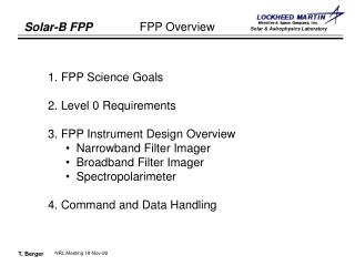
1. FPP Science Goals • 2. Level 0 Requirements • 3. FPP Instrument Design Overview • Narrowband Filter Imager • Broadband Filter Imager • Spectropolarimeter • 4. Command and Data Handling NRL Meeting 18-Nov-99
Primary FPP Science Goals • Magnetic Flux Transport • Observe how magnetic flux emerges, disperses, and disappears from the solar surface, including weak internetwork fields (B ~400 G). • Determine whether magnetic field is generated in or near the surface: fast dynamo action. • Convective Energy Scales • Understand the origin of the granulation, mesogranulation, and supergranulation. • Sunspots and Active Regions • Determine the vector magnetic field of sunspots and plage. • Observe the formation, dynamics, and decay of entire active regions. • Upper Atmospheric Connections • Understand the role of the surface magnetic field in the structure and dynamics of the outer atmosphere. • Solar Cycle Evolution • Understand the role of active regions in solar cycle modulation. NRL Meeting 18-Nov-99
Level 0 Requirements • Vector magnetic field measurement • Polarmetric precision > 0.01%: measure elemental flux tubes. • Spatial Resolution 0.2 arcseconds • Preserve imaging fidelty of SOT from 3800 - 6800 A. • Field of view O(100 arcseconds) • Capture entire active regions and significant portions of surrounding quiet network. • Image stabilization system • Stabilize SC jitter to < 0.02 arcsec over range of 2 -- 30 Hz. • Science Instruments • Narrowband Tunable Filter: wide FOV, fast cadence magnetograms and dopplergrams. • Broadband Filter Instrument: highest spatial and temporal resolution filtergrams. • Spectropolarimeter: <0.01% precision Stokes vector measurements. NRL Meeting 18-Nov-99
SOT/FPP Design Summary • SOT: Solar Optical TelescopeakaOptical Telescope Assembly (OTA) • 1/2-meter class for 0.2 arcsecond resolution in visible. • Axisymmetric design for minimal instrumental polarization. • OTU: Optical Transfer Unit • Polarization modulator • Tip/Tilt Mirror • NFI: Narrowband Filter Imager • Tunable Lyot filter: maximum FOV with uniform bandwidth • BFI: Broadband Filter Imager • Interference filters for maximal bandwidth and low optical distortion. • SP: Spectropolarimeter • Fe I 6302A line: fixed retardation rotating modulator for high precision Stokes polarimetry. • CT: Correlation Tracker • Real-time cross-correlation with updated reference image drives Tip/Tilt mirror. Optical Bench Unit (OBU) NRL Meeting 18-Nov-99
SOT/OTA System Overview • 0.5 meter Gregorian Telescope • Primary focal plane allows heat rejection mirror and “field stop” for optimal thermal control. • 400” X 400” FOV defined by field stop. • Diffraction limited wavelength range: 3968 (3800 goal) to 6700 A • Collimator Lens Unit (CLU) • Passes collimated 30 mm beam to OTU with known pupil location. • UV and IR rejection filters at field stop reduce heat load on focal plane. NRL Meeting 18-Nov-99
OTU System Overview • Polarization Modulator • Immediately follows CLU for optimal polarization modulation. • Quartz substrate ~0.25 wave retarder and linear polarizer at 6302 . • 1.6 second rotation period. • DC hollow core motor - continual operation throughout mission lifetime. • Multiple wedged optics to minimize beam wobble (POLIS design). • Tip/Tilt Mirror System • ISAS design and manufacture. • Provides 2-axis image stabilization of 0.02 arcseconds up to 30 Hz bandwidth. NRL Meeting 18-Nov-99
NFI System Overview • Tunable Lyot Filter System • 9-calcite wide-field elements in series. • Hollow-core DC motor control - fully sealed chamber. • Temperature calibrated. • 0.2 arcsecond spatial resolution over range from 5100 -- 6600 A. • 0.3 - 1 second temporal resolution for filtergrams; 0.1 second for Stokes images. • Spectral resolution 60--100 mA. • Polarization precision 0.1 - 1 %. • FOV selectable via focal plane mask • 320” x 160” wide FOV (some vignetting in corners) for filtergrams, dopplergrams, and longitudinal (Stokes V) magnetograms. • 160” x 160” active region FOV. • 80” x 160” narrow FOV for full Stokes vector mapping (I,Q,U,V) in 10 seconds. • Common Focal plane with BFI • 2048 x 4096 back illuminated frame transfer CCD, 0.08 arcsecond pixels. NRL Meeting 18-Nov-99
NFI Observables • Filtergrams • Arbitrary wavelength within in any line and nearby continuum. • Dopplergrams • Made on-board by FPP computer from 4 or more filtergrams in a line • Longitudinal Magnetograms • Made on-board by FPP computer from filtergrams converted to Stokes I & V. • Stokes Vector Elements • I, Q, U, and V made on-board from filtergrams taken at 6--8 phases of the polarization modulator. • Shutterless mode for higher time resolution or sensitivity but with smaller FOV. • On-board processing in FPGA smart memory similar to SP algorithm. NRL Meeting 18-Nov-99
Ion Wavelength g,eff Purpose Mg Ib 5172.7 A 1.75 Low chromosphere magnetograms, dopplergrams, Stokes vectors Fe I 5247.1 2.00 Secondary photospheric magnetic line. Fe I 5250.2 3.00 Used with 5247 line for ratio analyses. Fe I 5250.6 1.50 “ Fe I 5576.1 0.00 Photospheric dopplergrams Fe I 6301.5 1.67 Secondary photospheric magnetic line Fe I 6302.5 2.50 Primary photospheric magnetic line Stokes comparisons with SP Ti I 6303.8 0.92 Sunspot umbral magnetogram line HeNe 6328.1 Laser alignment and testing line H I 6563 H-alpha chromospheric filtergram and dopplergram line. NFI Spectral Lines NRL Meeting 18-Nov-99
BFI System Overview • Provides filtergrams with highest possible spatial and temporal resolution over largest FOV: maximize telescope useage. • FOV: shutter selectable • 160” x 160” CCD center area (2048 x 2048 0.08 arcsecond pixels) • 320” x 160” CCD full array exposure (4096 x 2048 0.08 arcsecond pixels) • Spectral range 3880 -- 6800 A • Temporal resolution < 5 sec for 160 x 160 arcsec FOV • Photometric Accuracy < 2% for continuum irradiance measurement. • Common Focal Plane with NFI • 2048 x 4096 back illuminated frame transfer CCD, 0.08 arcsecond pixels. NRL Meeting 18-Nov-99
BFI Interference Filters Center FWHM Purpose 3883.5 A 10 CN molecular bandhead: chromospheric network 3968.5 A 3 Ca II H-line: magnetic elements in low chromosphere 4305.0 A 10 CH G-band molecular bandhead: magnetic elements in photosphere; convection flowmapping. 4505.5 A 5 Blue continuum window 5550.5 A 5 Green continuum window Measure continuum irradiance 6684.0 A 5 Red continuum window NRL Meeting 18-Nov-99
SP System Overview • F/31 Littrow design • Off-axis paraboloid mirror avoids Littrow lens radiation damage issues. • Slit: 160” x 0.16” • Maximum map FOV = 320” x 160” (2000 raster steps of 0.16” each). • Dual-beam polarization analysis • Calcite prism gives +(Q,U,V) and -(Q,U,V) beams simultaneously on detector. • Fe I 6301.5 A (g=1.67) and 6302.5 A (g=2.5) lines • Spectral resolution < 35 mA • Spectral range > 2 A • Polarization precision ~ 0.01 % • Polarization S/N for map > 103 NRL Meeting 18-Nov-99
SP Observing Modes • Normal Mapping Mode • Expose/read/demodulate for 3 modulator rotations (4.8 seconds). • Optionally, move the slit one step of 0.16 arcsec (takes 0.1--0.2 sec). • Reduce I/Q/U/V spectra to 12 bits by shifting or look-up table. • Send to MDP for compression and downlink. • Raw data rate = 218 kPixels/sec. • 160” raster takes ~80 minutes, 320” raster takes ~160 minutes. • Fast Map Mode • Expose/read/demodulate for 1 modulator rotation, step the slit 0.16 arcsec, Expose/read/demodulate for 2nd rotation and add results: 0.32” raster sample. • On-chip sum 2 pixels in spatial direction (along slit): effective pixel size is 0.32” x 0.32”. • Convert to 12 bits, send to MDP. • Raw data rate = 146 kPixels/sec. • 1” raster takes ~10.9 seconds, 160” arcsecond raster takes ~29 minutes. NRL Meeting 18-Nov-99
Command & Data Handling Overview • MDP Interface • Science data: 16 bit serial interface (nominal 512 KHz). • Command and housekeeping data (64 KHz). • Filtergraph Ready/Busy status line. • Spectropolarimeter Ready/Busy status line. • Macro-commands initiate complex observables • Spectrograph maps. • Filtergraph Stokes maps. • Longitudinal magnetograms. • Dopplergrams. • CT reference image acquisition. NRL Meeting 18-Nov-99