Download
1 / 52
520 likes | 986 Views
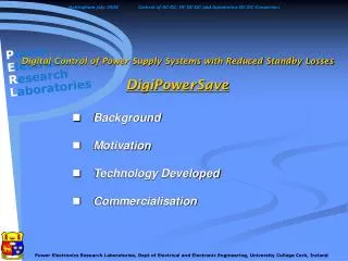
Digital Control of Power Supply Systems with Reduced Standby Losses DigiPowerSave. Background Motivation Technology Developed Commercialisation. Background.

E N D
Digital Control of Power Supply Systems with Reduced Standby LossesDigiPowerSave • Background • Motivation • Technology Developed • Commercialisation
Background • Regenerative electronic load for testing microprocessor Voltage Regulator Modules (VRM) developed under PRP/00/PEI/02b, “High Current/Low Voltage Converters for Environmentally Friendly Energy “ • System demonstrated at IEEE APEC and Electronica. • Detailed negotiations with companies to license this technology. • Elements of this technology are now being commercialised demonstrate MOSFET/Drivers.
2005 MOSFET Demonstrator • Follow-on project due completed in November 2006. • Observation: It appears easier to sell “technology development” than to license technology ?
Motivation for DigiPowerSave • Off-line, or mains-fed power supplies consist of two parts, • a front-end rectifier or ac/dc converter, to draw raw power from the mains • a second precision dc/dc converter to feed the low voltage electronic circuits. • Arising out of PRP/00/PEI/02b , we had developed digital techniques for front-end ac/dc converters. • From our experience in industrial motor drive technology, it was clear that digital control would also extend to the dc/dc power supply world. • Digital control can bring major advantages to both of these converter technologies.
Potential for Digital Control in Off-Line Power Supplies • Input AC/DC Converter Stage • Standby power in off-line power supplies uses 30W in every home in Ireland. • Up to €35 million, or 5% of residential consumption, is wasted every year, resulting in quarter of a million tonnes of CO2 generated. • Digital control enables the use of non-linear topologies to optimise efficiency and minimise standby loss. • Network communications facilitates remote power supply control. • Output DC/DC Converter Stage • Accurate and precise PWM control. • Potential for optimised adaptive control algorithms. • Reduced sensor requirements. • Digital communications with front-end ac/dc converter can help in overall system efficiency.
Typical power supply unit • Objectives:- • To address the growing environmentalissue of stand-by energy loss and maximise efficiency. • To optimise the advantages of emerging digital control techniques to produce a tightly controlled dc output voltage. • Applications include power supplies for a wide range of electronic products.
ATRP/01/314 DigiPowerSave Innovation in Digital AC/DC Converter Control • Use of novel topologies • Digital technology allows non-linear control strategies not possible using analogue schemes • Alternative sensing arrangements can be implemented • Extra magnetics can be eliminated, improving manufacturability • Special standby modes • Burst operation when power levels are low • Introduction of low- power standby function • Reduction of intermediate bus voltage during standby • This also increases reliability of electrolytic capacitors • Hold-up capacities can be folded back
ATRP/01/314 DigiPowerSave Topology Implementation • Two prototypes power supplies were developed • A 65W two-switch flyback • No power factor correction is required below 70W • Typical power level for dvd players and set-top boxes • Supply controlled by DSP on secondary • Secondary post regulation was used for standby operation • A 200W novel topology • 12V output to be cascaded with high spec dc-dc • Typical configuration for computer supplies • DSP on the primary, microcontroller on the secondary • Intermediate bus voltage reduced for standby operation
ATRP/01/314 DigiPowerSave 65W Two-Switch Flyback • Secondary Side DSP control • Low power TopSwitchtm-fed winding on the same transformer for start-up • Output filter inductor is used as a buck when in standby mode
ATRP/01/314 DigiPowerSave Efficiency in Normal Mode
ATRP/01/314 DigiPowerSave Efficiency in Standby Mode
ATRP/01/314 DigiPowerSave Power Flow in an Off-Line PSU Required Output Power Mains Input Power Power stored in the bus caps Power from bus caps Power from bus caps Power goes directly to the output
Topology Characteristics • Benefits • Only a single magnetic is required • 70% of the power requires only one “conversion” • No inrush current, no NTC thermister required • Intermediate bus voltage can be reduced • Drawbacks • 2 high-side gate drives required • Fast recovery rectifier diodes required • Primary leakage results in re-circulating energy • Discontinuous currents
ATRP/01/314 DigiPowerSave 200W Prototype • Only one custom magnetic component • Efficiency 83% to 87%
ATRP/01/314 DigiPowerSave Future possibilities • The digital strategies and technology developed in this project could also be applied to • Power supplies with integral UPS features • Integration of small scale generation with a household supply • Solar panels • Small wind turbines • Micro CHP • Integration of power supplies with building management systems
Digital control in dc-dc conversion • Divides into two separate applications: • Digital control loop (high-frequency) • System monitoring/interfacing (low-frequency) • Project focus on digital control loop • Development of hardware modules • High-frequency, high-resolution pulse generation • Generation of multiple matched and phase-delayed signals requiring area-efficient implementation • FPGA-based architectures with frequency calibration capability • Algorithm development • Observer-based control Power Electronics Research Laboratories, Dept of Electrical and Electronic Engineering, University College Cork, Ireland
Generation of multiple high-frequency, high-resolution pulsed digital signals Reduced cost of current sensors Typical dc-dc buck converter architecture Project development: Power Electronics Research Laboratories, Dept of Electrical and Electronic Engineering, University College Cork, Ireland
High resolution pulse generation • Delay line approach • Minimises required clock frequencies • Uses logic gates as delay elements • Difference in time delay between paths allows very high resolution pulses to be generated. Power Electronics Research Laboratories, Dept of Electrical and Electronic Engineering, University College Cork, Ireland
High resolution pulse generation • UCC approach uses 3 delay granularities • Minimises required implementation area • Achieves very high resolution (~ 255 ps) Power Electronics Research Laboratories, Dept of Electrical and Electronic Engineering, University College Cork, Ireland
High resolution pulse generation • Architecture expanded to generate multiple outputs • Phased nature of outputs used to reduce implementation area compared to non- optimised architecture Power Electronics Research Laboratories, Dept of Electrical and Electronic Engineering, University College Cork, Ireland
ATRP/01/314 DigiPowerSave Commercialisation I • Two digitally controlled PSU’s have been developed • A 65W supply for set-top box applications • A 200W single magnetic unit with integrated power factor correction. • Intellectual property • Novel single magnetic topology • Application of state space methods to PSU control • Potential for commercialisation • Discussions with large IC company regarding PSU digital control. • Support for Irish power supply companies wishing to incorporate digital control into their products • Licensing of novel topology to be further explored.
ATRP/01/314 DigiPowerSave Commercialisation II • June, 2005, 'A digital PWM controller for multi-phase dc/dc converters' (DigiPowerSave). This patent was allowed to lapse as it was not licensed. • Discussions with large IC companies regarding the use of high resolution PWM generation
The comparative non-isolated bi-directional dc-dc converter analysis Marek Rylko
Aim of the work • Comparative half-bridge bi-directional high-power dc-dc converter analysis • Switching regimes (soft and hard switching) • Switching devices (MOSFET, IGBT, diode) • Materials (silicon, SiC, GaN) • Operating frequency limits • Volume and cost analyses • Magnetic design • An inductor • An transformer
Introduction • The hi-power dc-dc converter application • Automotive (power train) • Battery chargers • Fuel Cell stationary generators • Wind turbines (potentially) • Electric crafts Regenerative Load DC-DC Converter Battery SuperCap
The Power Requirement • Power requirement depends on design i.e.: • The automotive application for mid-size C class car 100kW peak for 30sec and 50kW continuous power – competitive performance to present ICE cars • The battery charger - maximum charging current and voltage (charging regimes) • Consideration of the work-cycle is important to avoid an overestimated design
The Power Supply • The internal combustion engine with generator (gasoline, diesel, CNG, LPG, hydrogen, methanol) • Pollution (NOx, CO and CO2) • Crude Oil shortage • The fuel cell • Zero emission (excluding hydrogen production) • Refuelling problem, low social acceptance • Short Cycle Lifetime • The battery • Well established technology, clean but expensive and requires complex production process, contains toxic components, recycling problem • The solar panel • Low power density, solar radiation dependent
The Car Power Train • Classical solutions with IEC • Hybrid propulsion systems (IEC and electric motor) • Series Hybrid • Parallel Hybrid • Series-Parallel • Complex Hybrid • The battery electric vehicle • The fuel cell electric vehicle
The Fuell Cell • Fuell Cell types and properties • Types PEM, AFC, PAFC, MCFC, SOFC • fuel cell operates best at a 30 percent load factor due to issue of mass transport limitation (oxygen and hydrogen contact with membrane) • Ironically, the fuel cell does not eliminate the battery – it promotes it. The fuel cell needs batteries as a buffer. • Efficiency up to 65% at 30% of load (efficiency is output power reffered to LHV – includes water vaporisation) • Complex auxiliary components system • Auxiliary system requires 10-15% of FC rated power • High cost
Batteries • The Battery - types and properties • Types: Valve Regulated Lead Acid (VRLA), NiCd, NiZn, NiMH, Zn/Air, Al/Air, Na/S, Na/NiCl2, Li-Polymer, Li-ion, • High efficiency up to 99% (Li-ion polymer exclude converter) • Zero emission (energy generation not included) • Specific energy 330Wh/kg Li-ion superpolymer Electrovaya • Specific power 315W/kg at 80% discharge rate (Li-ion polymer) • Energy density 600Wh/liter Li-ion superpolymer Electrovaya • High cost (>100€/kWh Li-ion) • Short lifetime (800-1200 at 80% discharge rate Li-ion) or 3-7 years • Toxic component – needs recycling policy • Battery terminal voltage varies with state of charge and discharge current (1.6-2.4V for VLRA, 3-4V for Li-ion) • Charging issues • Super Capacitor
The Load • 4-quadrant inverter with electric motor • Energy recovering • Energy conditioning for double-fed induction motor
The Converter • Isolated – push and pull, full bridge • Non-isolated – half-bridge buck-boost, cascade, buck, boost, CUK, Sepic/Luo, voltage multipliers (magnetic-less) • Hard switched (HS) • Soft switched (SS) • Simplicity • Bi- and uni-directional • Advantages and disadvantages Non-isloated HS converter Non-isolated SS converter Isolated converter
Hard and Soft Switching The Hard Switching Switching losses limit the maximum operating switching frequencyandmay result in significant device derating. The soft switching constrains the switching of the power devices to time intervals when the voltageacross the device or the current through it is nearly zero. The Soft Switching
Semiconductor Devices • Materials • Silicon • Silicon Carbide (SiC) • Gallium(III) Nitride (GaN) • Devices • MOSFET (CoolMOS) • IGBT (Trench, Planar) • BJT • Thyristor
Magnetics • Inductor • High inductance dc inductor with small ac-component – small current ripple • Low inductance dc inductor with high ac-component – high current ripple • Transformer • Magnetising inductance issue • Power loss associated • Core (histeresis, eddy currents) • Windings (eddy currents – skin and proximity effect)
Soft-Switching Converter The converter has been made by adding an auxiliary cell to the classical half-bridge bi-directional converter.
Soft-Switching Converter • The presented soft-switched converter is quasi-resonant with an auxiliary commutation cell • Benefits of solution are: • Use intrinsic MOSFET body diodes • High efficiency over a wide load range up to 97.6%* • High operating frequency leading to size reduction • Very robust, topology ensuring safe operating region by hardware design • Works above audible frequency 100kHz • Disadvantages • More elements than classical solution • Auxiliary signals • Complicated design process *For V1/V2 = 0.5
The Duty Cycle Analysis • The converter is assumed to operate under fixed bus voltage conditions and the converter average output current gain is investigated • The pole-voltage wave shape is affected by the turn-on and turn-off mechanisms • The converter current gain can differ significantly from the idealised HS case Pole voltage HS ideal SS cell
HS SS The Duty Cycle Numerical Verification The HS and the SS case differs due to SS V·s loss Gray points represents PSpice™ simulation results
Converters comparison • Three converters have been built and tested • Soft-switched MOSFET based – low ripple • Hard-switched MOSFET based – high ripple
Converters comparison • Hard-switched IGBT based – low ripple Table I. Converters comparison
Converters comparison • Switching Devices • MOSFET - Infineon type SPW47N60 (CoolMOS™) • IGBT - International Rectifier type IRGP50B60 (WARP2) • Auxiliary MOSFET - Infineon type SPP12N50C3 (CoolMOS™) • Inductors • Low-ripple inductor made of solid wire ø1.5mm, 19 turns, 200H, core EE65, material 3F3, total airgap 1.44mm • High-ripple inductor made of Litz wire 25xø0.315mm, 7 turns, 28H, core EE65, material 3F3, total airgap 2.38mm
The Test Rig Inductor Main pole The Soft-switching cell Control board
The Control Board Based TMS320F2808
Conclusions • Bi-directional converters have been investigated only • The three converters, which have been presented, achieve high efficiency of order 96-97% over a wide load range • Low-ripple HS MOSFET on test shows efficiency of order 88% due to the poor intrinsic diode • The IGBT transistor with the soft-switching cell did not demonstrate any significant efficiency improvements • The HS-converters with the IGBT transistors are preferred at frequencies up to 150kHz due to lower cost and simplicity • Beyond 150kHz MOSFETs indicates superiority over IGBTs • High-ripple converter, despite great efficiency results, cause serious challenge for magnetic design due to significant current AC component