Download
1 / 18
180 likes | 205 Views
Comprehensive presentation on aerobatic maneuvers with detailed diagrams and scoring guidelines for judges training.

E N D
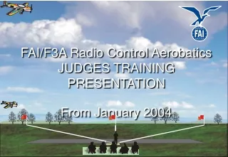
MAAC Precision Aerobatics JUDGES TRAINING PRESENTATION 2016
SCHEMATIC MANEUVER DIAGRAMS MAACSPORTSMAN
1 - Takeoff • It is not necessary for the model to stand still on the ground with the engine running without being held before the takeoff begins. • It is also not necessary for the model to reach 2 meters in the same distance as the takeoff roll. • The takeoff should not be downgraded for wing dips caused by air turbulence unless the wings are not immediately leveled. Downgrades • Model jumps from the ground. • Retouches the ground after becoming airborne. • Steep climb angle. • Gallops in elevation during climb. • Wings not level at any time. • Model does not acceleratesmoothly. • Model passes behind the judges line, scored zero (0) points. The maneuver is complete when the model is approximately two (2) meters (6-1/2 feet) from the ground.. The lift off should be within two (2) meters of center for maximum points.
2 – (U) Straight Flight Out • The model must be brought exactly parallel to the flight path and flown in an absolutely straight and level path for a distance of approximately 100 meters centered on the judges (distance does not have to be accurate.). • Track of plane deviates left or right. • Does not hold constant altitude. • Gallops in yaw, roll, or pitch. Straight and level exit Straight and level entry
3 – Procedure Turn • First turn not exactly 90°. • Opposite turn not exactly 270° • Changes in altitude during turns. • Turns not smooth and circular. • Does not head back over exact outgoing path. 270° Constant-Radius Turn 90° constant-Radius Turn Straight and level exit - heading and path opposite of entry Straight and level entry
4 – (D) Straight Flight Back (Exit Box) • The model shall fly back along the same line as the outgoing path. • The model must be brought exactly parallel to the flight path and flown in an absolutely straight and level path for a distance of approximately 100 meters centered on the judges (distance does not have to be accurate.). • Track of plane deviates left or right. • Does not hold constant altitude. • Gallops in yaw, roll, or pitch. • Flight path not along straight flight out path Straight and level entry Straight and level exit
5 – (U) (Enter Box) One Inside Loop • Loops not round. • Loops not superimposed. • Wings not level during loops. • Changes in heading (track) during loops. • Exit not same altitude and heading (track) as entry. Straight and level entry Straight and level exit
6 – Immelman Turn Straight and level exit • Model not level at start or finish. • Roll not immediately after half loop. • Changes in heading (track) after half loop or prescribed roll. • Model track does not finish exactly opposite direction of entry. • Half loop not round. • Over or under rotation on prescribed roll, one point per 15-Degree rule. 1/2 loop Straight and level entry
Straight and level entry 1/2 loop Straight and level exit 7 – Split S (Exit Box) • Half roll not 180 degrees. • Half loop not started immediately after half roll. • Half loop not constant radius. • Changes in heading (track) • One-half (1/2) roll not in level flight. • Model heading (track) does not finish exactly opposite the direction of entry. • Wings not level during loop segment.
8 - (D) One Horizontal Roll • Changes in heading (track) during rolls. • Changes in altitude during rolls. • Roll rate not constant. • Model does do exactly one roll (1 pt/15º rule) Straight and level exit Straight and level entry
5/8Loop 1/8 Loop Straight and level exit 9 – Half Reverse Cuban 8 • Loop segments not round and of same radius. • Model track not at 45 degrees before and after half roll. • Changes in heading (track) during half roll. • Half roll not on center of 45-degree line. Straight and level entry • NOTE: In a TA maneuver, entry and exit altitude changes are allowed. To change altitude in this maneuver, the 45 degree line may be extended or truncated. All loop radii must remain equal.
Straight and level entry Straight and level exit 10 – (U) Cobra Without Rolls (Exit Box) • Climb and dive not 45º • Changes in heading (track) • Loop segments not round with same radius. • Entry and exit not at same altitude 1/4 loop 1/8 loop 1/8 loop
Straight and level entry Straight and level exit 11 – (D) (Enter Box) Straight and Level Flight • Track of plane deviates left or right. • Does not hold constant altitude. • Gallops in yaw, roll, or pitch. • Maneuver off-center
Loop segments not round and of same radius. • Model track not at 45 degrees before and after half roll. (1 pt / 15º rule) • Changes in heading (track) during half roll. • Half roll not on center of 45-degree line. 5/8Loop 1/8 Loop Straight and level exit Straight and level entry • NOTE: In a TA maneuver, entry and exit altitude changes are allowed. To change altitude in this maneuver, the 45 degree line may be extended or truncated. All loop radii must remain equal. 12 – Half Cuban 8
Straight and level exit Straight and level entry 13 – (D) Straight and Level Flight • Track of plane deviates left or right. • Does not hold constant altitude. • Gallops in yaw, roll, or pitch. • Maneuver off-center
14 – Stall turn (Exit Box) • Stall turn direction is pilot’s options • Model not level at start and finish • Track does not become exactly vertical • Track not vertical at beginning and end of rolls and stall turn. • Return path not parallel to entry path • Track of stall turn not 180 degrees. 1/4 loop • Pivot not on CG. • Loop segments not round and of equal radius. • Pendulum movement after stall. • Exit not same altitude and heading (track) as entry. Straight and level Exit Straight andlevel entry
15 – (Enter Box) Rectangular Approach • The manoeuvre commences with the model flying straight and level into wind over the takeoff line, a turn of 90 degrees, a crosswind leg, a second turn of 90 degrees, a downwind leg, a third turn of 90 degrees, a crosswind leg, a fourth turn of 90 degrees and straight flight towards the point of touchdown • The first three legs will be at constant altitude • Descent to touchdown will commence after the second crosswind leg. • The manoeuvre is completed just prior to two meters from the ground. Constant Altitude
Landing zone (white) and Landing area (green) shown below. • Landing zone is 30 m wide and normally the width of the runway BUT not more than 30 M deep. Runway width up to 30 m Landing zone 30 m 16 – Landing • Model passes behind the judges line, zero (0) points. • Model impacts the runway due to lack of flare. • Model bounces. • Changes in track. • Model ends on its back, zero (0) points. • Model lands outside landing zone (but still on runway). • If any undercarriage retracts before the landing is complete, zero (0) points. • Aircraft “porpoises” and/or wanders during approach or flare. • Aircraft lands outside the landing area or runway, zero (0) points. • Aircraft touches down while not straight to runway and ground track. The landing will not be downgraded if: • The model rolls to a controlled stop within 10 meters. • Wing dips which are caused by air turbulence unless they are not immediately corrected. • The pilot “slips to a landing” to handle a crosswind condition in which case a wing will be low • Displacement of the touchdown point left or right as long as the landing is in the landing zone Landing begins when the model is approximately two (2) meters (6-1/2 feet) from the ground. Landing area:the entire defined runway