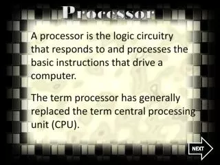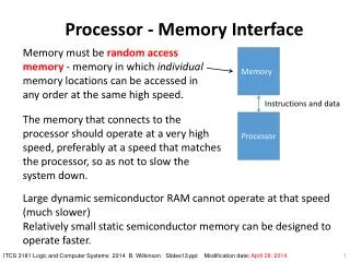
Keyboard Input Handling and Interrupt Processing in Computer Architecture
This document outlines the process of handling keyboard input through interrupts in a computer system. It details the structure of single-bus architectures, memory initialization, and the steps taken to read a line of characters. Key programming movements are highlighted, including the manipulation of status registers, handling of carriage return, echoing input to display, and interrupt service routines. It also illustrates the implementation of input/output interfaces, along with relevant circuit diagrams for better understanding.

Keyboard Input Handling and Interrupt Processing in Computer Architecture
E N D
Presentation Transcript
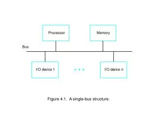
Processor Memory Bus I/O de vice 1 I/O de vice n Figure 4.1. A single-bus structure.
Mo v e #LINE,R0 Initialize memory p oin ter. W AITK T estBit #0,ST A TUS T est SIN. Branc h=0 W AITK W ait for c haracter to b e en tered. Mo v e D A T AIN,R1 Read c haracter. W AITD T estBit #1,ST A TUS T est SOUT. Branc h=0 W AITD W ait for displa y to b ecome ready . Mo v e R1,D A T A OUT Send c haracter to displa y . Mo v e R1,(R0)+ Store c haracter and adv ance p oin ter. Compare #$0D,R1 Chec k if Carriage Return. Branc h 0 W AITK If not, get another c haracter. Mo v e #$0A,D A T A OUT Otherwise, send Line F eed. Call PR OCESS Call a subroutine to pro cess the input line. Figure 4.4 A program that reads one line from the keyboard stores it in memory buffer, and echoes it back to the display.
V dd Processor R I N T R INTR INTR1 INTR2 INTR n Figure 4.6. An equivalent circuit for an open-drain bus used to implement a common interrupt-request line.
Figure 4.7. Implementation of interrupt priority using individual interrupt-request and acknowledge lines.
Please see “portrait orientation” PowerPoint file for Chapter 4 Figure 4.8. Interrupt priority schemes.
Main Program Mo v e #LINE,PNTR Initialize buffer p oin ter. Clear EOL Clear end-of-line indicator. BitSet #2,CONTR OL Enable k eyb oard in terrupts. BitSet #9,PS Set in terrupt-enable bit in the PS. . . . In terrupt-service routine – READ Mo v eMultiple R0-R1, (SP) Sa v e registers R0 and R1 on stac k. Mo v e PNTR,R0 Load address p oin ter. Mo v eByte D A T AIN,R1 Get input c haracter and Mo v eByte R1,(R0)+ store it in memory . Mo v e R0,PNTR Up date p oin ter. CompareByte #$0D,R1 Chec k if Carriage Return. 0 Branc h R TRN Mo v e #1,EOL Indicate end of line. BitClear #2,CONTR OL Disable k eyb oard in terrupts. R TRN Mo v eMultiple (SP)+,R0-R1 Restore registers R0 and R1. Return-from-in terrupt Figure 4.9. Using interrupts to read a line of characters from a keyboard via the registers in Figure 4.3.
Please see “portrait orientation” PowerPoint file for Chapter 4 Figure 4.10. A few operating system routines.
Please see “portrait orientation” PowerPoint file for Chapter 4 Figure 4.12. Accessible registers in different modes of accessible processors.
Please see “portrait orientation” PowerPoint file for Chapter 4 Figure 4.13. An ARM interrupt-service routine to read an input line from a keyboard based on Figure 4.9.
Main program MO VE.L #LINE,PNTR Initialize buffer p oin ter. CLR EOL Clear end-of-line indicator. ORI.B #4,CONTR OL Set bit KEN. MO VE #$100,SR Set pro cessor priorit y to 1. . . . In terrupt-service routine – READ MO VEM.L A0/D0, (A7) Sa v e registers A0, D0 on stac k. MO VEA.L PNTR,A0 Load address p oin ter. MO VE.B D A T AIN,D0 Get input c haracter. MO VE.B D0,(A0)+ Store it in memory buffer. MO VE.L A0,PNTR Up date p oin ter. CMPI.B #$0D,D0 Chec k if Carriage Return. BNE R TRN MO VE #1,EOL Indicate end of line. ANDI.B #$FB,CONTR OL Clear bit KEN. R TRN MO VEM.L (A7)+,A0/D0 Restore registers D0, A0. R TE Figure 4.15. A 68000 interrupt-service routine to read an input line from a keyboard based on Figure 4.9.
Main program MO V EOL,0 MO V BL,4 OR CONTR OL,BL Set KEN to enable k eyb oard in terrupts. STI Set in terrupt flag in pro cessor register. . . . In terrupt-service routine READ PUSH EAX Sa v e register EAX on stac k. PUSH EBX Sa v e register EBX on stac k. MO V EAX,PNTR Load address p oin ter. MO V BL,D A T AIN Get input c haracter. MO V [EAX],BL Store c haracter. INC D W ORD PTR [EAX] Incremen t PNTR. CMP BL,0DH Chec k if c haracter is CR. JNE R TRN MO V BL,4 X OR CONTR OL,BL Clear bit KEN. MO V EOL,1 Set EOL flag. R TRN POP EBX Restore register EBX. POP EAX Restore register EAX. IRET Figure 4.17. An interrupt-servicing routine to read one line from a keyboard using interrupts on IA-32 processors.
Figure 4.21. Sequence of signals during transfer of bus mastership for the devices in Figure 4.20.
Please see “portrait orientation” PowerPoint file for Chapter 4 Figure 4.29. Input interface circuit.
Please see “portrait orientation” PowerPoint file for Chapter 4 Figure 4.32. Output interface circuit.
Please see “portrait orientation” PowerPoint file for Chapter 4 Figure 4.33. Combined input/output interface circuit.
Please see “portrait orientation” PowerPoint file for Chapter 4 Figure 4.34. A general 8-bit parallel interface.
Please see “portrait orientation” PowerPoint file for Chapter 4 Figure 4.35. A parallel point interface for the bus of Figure 4.25, with a state-diagram for the timing logic.
T ime 1 2 3 Clock Address R/ W Data Go Sla v e-ready Figure 4.36. T iming for the output interf ace in Figure 4.35.
Please see “portrait orientation” PowerPoint file for Chapter 4 Figure 4.37. A serial interface.
Please see “portrait orientation” PowerPoint file for Chapter 4 Figure 4.38. An example of a computer system using different interface standards.
T ar gets e xamine ID D B 2 D B 5 D B 6 B S Y S E L Free Arbitration Selection Figure 4.42. Arbitration and selection on the SCSI bus. Device 6 wins arbitration and selects device 2.
Please see “portrait orientation” PowerPoint file for Chapter 4 Figure 4.43. Universal Serial Bus tree structure.
Please see “portrait orientation” PowerPoint file for Chapter 4 Figure 4.44. Split bus operation
Please see “portrait orientation” PowerPoint file for Chapter 4 Figure 4.45. USB packet format.
Please see “portrait orientation” PowerPoint file for Chapter 4 Figure 4.46. An output transfer.
Please see “portrait orientation” PowerPoint file for Chapter 4 Figure 4.47. USB frames.
Table 4.1. Interrupt vector addresses for ARM processor Address Exception Mo de en tered (hex) 0 Reset Sup ervisor 4 Undefined instruction Undefined 8 Soft w are in terrupt Sup ervisor C Ab ort during prefetc h Ab ort 10 Ab ort during data Ab ort 14 Reserv ed 18 IR Q IR Q 1C FIQ FIQ
Table 4.2. Address correction during return from exception. Exception Sa v ed address* Desired Return instruction return address Undefined instruction PC+4 PC+4 MO VS PC,R14 und Soft w are in terrupt PC+4 PC+4 MO VS PC,R14 sv c Prefetc h Ab ort PC+4 PC SUBS PC,R14 abt,#4 Data Ab ort PC+8 PC SUBS PC,R14 abt,#8 IR Q PC+4 PC SUBS PC,R14 irq,#4 FIQ PC+4 PC SUBS PC,R14 fiq,#4 * PC is the address of the instruction that caused the exception. F or IR Q and FIQ, it is the address of the first instruction not executed b ecause of the in terrupt.