FPD STATUS
FPD STATUS. JORGE MOLINA CBPF February 2002. Current FPD Group. UTA Andrew Brandt (faculty) Mike Strang (grad student) Pierrick Hanlet (post-doc) Christophe Royon (Saclay faculty) Victor Bodyagin (Moscow State faculty) Jia Li (engineer/physicist) Tom Lytle (grad student) Brazil

FPD STATUS
E N D
Presentation Transcript
FPD STATUS JORGE MOLINA CBPF February 2002
Current FPD Group • UTA • Andrew Brandt (faculty) • Mike Strang (grad student) • Pierrick Hanlet (post-doc) • Christophe Royon (Saclay faculty) • Victor Bodyagin (Moscow State faculty) • Jia Li (engineer/physicist) • Tom Lytle (grad student) • Brazil • Alberto Santoro (faculty) • Sergio Novaes (faculty) • Jorge Molina (grad student) • Gilvan Alves (faculty) • Helio da Motta (faculty) • Newton Oliveira (engineer) • Eduardo Gregores (post-doc) • Mario Vaz (engineer) • Jorge Barreto (faculty) • Vitor Oguri (faculty) • Carley Martens (faculty) • Marcia Begalli (faculty) • Andre Sznajder (post-doc) • Wagner Carvalho (post-doc) • Other • Mike Martens (FNAL) • Vladimir Sirotenko (FNAL) • Carlos Avila (Bogata) • S. Ahmed (Nijmegen) • Brian Cox (Manchester) (based at FNAL)
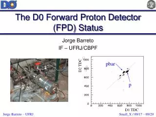
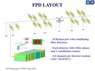
Castles Status • All 6 castles with 18 Roman pots comprising the FPD were constructed in Brazil and have been installed in the Tevatron in fall of 2000. Quadrupole castle A2 installed in the beam line.
P1U P2U A1U P2Q A2U Q3 Q4 Q4 Q3 Q2 S Q2 S D2 D1 A1D A2D P1D P2D 57 33 23 0 23 33 Detector Installation • 10 detector cartridges have been installed: 8 in the vertical plane, 2 at Dipole locations. • We expect to install the remaining 8 in the July 2002 shutdown (subject to funding for PMT’s). Z(m)
Detector Setup Six planes (u,u’,x,x’,v,v’) of 800 mm scintillating fibers (’) planes offset by 2/3 fiber 20 channels/plane(U,V)(’) 16 channels/plane(X,X’) 112 channels/detector 18 detectors 2016 total channels 4 fibers/channel 8064 fibers 1 250 mm LMB fiber/channel 8 LMB fibers / bundle 252 LMB bundles 80 mm theoretical resolution U’ U 4 fiber bundle fits well the pixel size of H6568 16 Ch. MAPMT 7 PMT’s/detector 16 250 mm fibers each PMT
Detector Asembly At the University of Texas, Arlington (UTA), scintillating and optical fibers were spliced and inserted into the detector frames.
Detector Mapping After the detectors were assembled and polished, an optical scanner was used to map the exact location and width of the fibers in the frames to improved detector calibration.
Detector Cartridges The two-part cartridge houses the detector and phototubes and allows for easy access to PMT’s. The Cartridge top fits over the bottom and is secured down causing good contact between the tubes and cookies
Detectors in Cartridges The cookies containing the other end of the fibers is attached to the cartridge bottom. The cartridge bottom is installed in the tunnel and the detector is pushed to the bottom of the pot.
Installed Cartridge A2 station with cartridges mounted in the vertical plane
Cartridges Status • All 18 cartridges are assembled. Ten cartridges are installed: • 6 of them are in their final configuration: • P1D, P2D, A1D,A2D,D1 and D2 • 2 of them contain prototype detectors: P1U • and P2U • 2 of them are pseudodetectors (trigger • scintillators only: A1U and A2U • All the MAPMT’s and L0 detectors were • grouped according to their characteristics • In February the installation of the remaining four detectors of Phase I will be completed
In the October shutdown four veto counters each of which cover 4.2 < || < 5.9 were installed between DØ and the quadrupoles, about 6 m from the interaction point. VETO COUNTERS The counters, two each on the outgoing proton and anti-proton arms, can be used to trigger on rapidity gaps.
POT MOTION Pot motion is performed by an FPD shifter in the DØ Control Room via a Python program that uses the DØ online system to send commands to the step motors in the tunnel. LVDT’s connected to the castle measure the actual pot displacement and return values giving the distance from the “Home” position of each pot.
Pot Motion Safeguards • The software is reliable and has been tested extensively. It has many safeguards to protect against accidental insertion of the pots into the beam. • The drivers are disabled with a switch in the Control Room when the pots are not being moved. • The pots are hooked to an emergency line which bypasses the software to send the pots back to the home position in case of • emergency (tested but not used).
Lumberjack Plots Effect of the pot motion over the proton and antiproton losses at D0 and CDF We should not affect the losses more than 20% under the risk of make the beam unstable
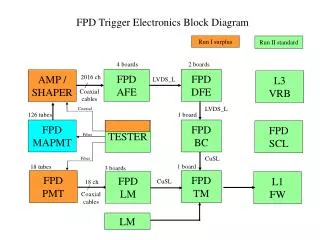
DAQ • Due to delays in DØ trigger electronics, • we have maintained our standalone DAQ first used in the fall 2000 engineering run. • We build the trigger with NIM logic • using signals given by our trigger PMT’s, • veto counters, DØ clock, and the luminosity • monitor. • If the event satisfies the trigger requirements, the CAMAC module will • process the signal given by the MAPMT’s. • With this configuration we can read the information of only two detectors (currently PD spectrometer is read out).
Standard DAQ In parallel, work continues on commissioning the standard Run II DAQ. The most recent progress was the construction and installation of the Transition Patch Panel and combs. We are working on the DFE FPGA logic and awaiting our complement of AFE boards, integration with DØ is scheduled over the next 3 months.
Plateau Curves The L0 PMT's were plateau using elastic eventa in a three fold/four fold basis:
Problems … A problem we had in the tunnel was due to noise caused by the (WWII surplus) low voltage power supplies used for the amplifier boards. They induced a current in the cables that added an extra peak in pedestal distribution.
and Solutions • The problem were solved by adding a new rack at each pot station in the tunnel with new high quality LVPS and isolation transformers (this configuration also isolates Tevatron and DØ noise sources). • ****Need new narrow pedestal plot here from victor
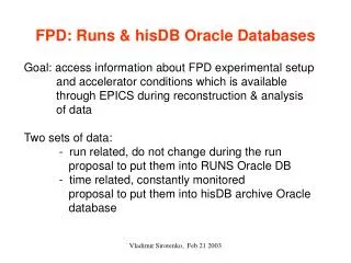
SOFTWARE UPDATE • Unpacking • Data unpacking utilities ready and released. • Mapping from detector to AFE channel ready. • Need calibration package for a final release • Tracking • Single track reconstruction implemented • MC ξ- and t-distributions obtained • Acceptance studies completed • Multi-track studies near completion • “Final “version in next release
Single Interaction Tool • Vetoes on multiple event vertices reconstructed in silicon • Maximum calorimeter energy cut included • Waiting for Luminosity Monitor information • Monte Carlo tests underway • Database • Pot positions and alarms in Oracle databases. Need to add the beam parameters to calculate beam positions, and expected pot positions from Python program.
Alignment • MC to study elastic events with FPD has been implemented • MC studies for alignment to investigate uncertainty on beam position • MC studies fro mmeasurements of total cross section using Tevatron injection lattice • Next steps: • Algorithm for Online alignment of the FPD detector • Procedure for total cross section and luminosity measurements • Gap Tool • Ready to include rapidity gap cuts at Level 2 of trigger
Plans and Milestones Take more data with Stand Alone DAQ with this configuration, then switch detectors to readouts (still for elastic events) Take diffractive data. TM operational 1/31/02 AFE installed 3/1/02 Firmware and Trigger development FPD data with 10 pot system 4/1/02 Prepare for the July shutdown: installation of the horizontal plane
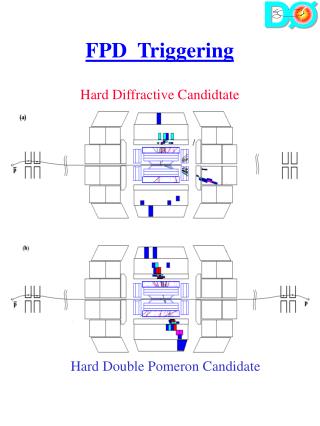
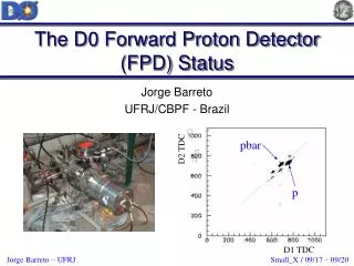
Hit Reconstruction • This event (from Engineering Run data) • represents a hit in our detector at the location: • xd = 5.6 mm • yd = 3.8 mm
Pot Motion Tests Initially pot motion tests restricted to end of stores, so progresss slow Eventually gained confidence of BD, allowed to insert pots anytime
Conclusions • Tremendous progress in installation and • commissioning • Entering a new FPD era: Installation of Phase I • complete • Emphasis shifts to software, operations, and data • analysis • Trigger hardware and firmware still a major • concern • Starting to think about physics a little!