
Understanding Computer Structure and Processor System Components
Learn about μProcessor, Bus, Memory, I/O Ports, and more. Study PPI, PIA, Volatile and Non-volatile Memory & detailed Microprocessor history.

Understanding Computer Structure and Processor System Components
E N D
Presentation Transcript
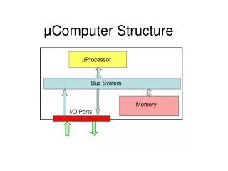
μComputer Structure μProcessor Bus System Memory I/O Ports
Word Word AD Converter DA Converter V V Driving Circuit Amplifier Hydraulic orElectricSignal mV Thermocouple Valve Temperature PPI (INTEL) 8255 , PIA (MOTOROLA) 6821I Port O Port Flow Control
Memory memory address content FFFFFH 78H Volatile: RAMs (R,W) 23H 00H 00002H Address Space D5H 00001H 29H Non-volatile: ROM, PROM, EPROM, EEROM 00000H F1H 20 bits 8 bits
The μProcessor Available in 40 Pins DIP • Performs arithmetic and logical operations • Decodes program instructions • Controls the μComputer operation • Contains some memory μP = CPU The 8086 or 8088 μP
Address Bus Data Bus Control Bus The System Bus The address bus contains 16 unidirectional lines The data bus contains 8 bidirectional lines The control bus is made of individual lines that are unidirectional in most of the cases, but sometimes are bidirectional
Program Execution Instruction register 5 6 Instructions & data 7 Instruction decoder Data Bus 8 Program counter 2 3 Address decoder 4 1 Address Bus μP memory
Introduction to μP Microprocessors and Peripherals Brey Merrill ISBN: 0-675-20884-X
How A 16 bit word is stored in 2 consecutive 8 bit memory locations ABH 00725H ABCDH 00724H CDH
Instruction Pointer AH AL IP BH BL Data Registers CH CL DH DL Status register CS SR DS 9 bits Segment Registers SS ES Pointer Registers SI SP Index Registers DI BP Software Model of the 8086 or 8088 μP 8086 or 8088 μP AX BX CX DX
Memory Segmentation Physical Address FFFFFH Code Segment 64KB XXXX0H Data Segment CS 64KB DS XXXX0H SS ES 64KB Stack Segment XXXX0H 64KB Extra Segment XXXX0H 00000H
Dedicated and General Use of Memory FFFFFH 12 Bytes reserved FFFEFH Open memory 80H 7FH 128 Bytes to store pointers to interrupt service routines Each pointer requires 4 memory locations reserved 0H
Physical &Logical Addresses Physical Address 0280BH 0280AH 0280BH 02809H 02808H 02807H 02806H Offset 000BH 02805H Logical Address 02804H 0280H:000BH 02803H 02802H 02801H Segment Base 02800H
Code Segment Instruction Pointer Logical address 8888H:1234H + 8888H 1234H Physical address 89AB4H Address of the next instruction to be executed 88880H+1234H = 89AB4H General purpose registers AX Accumulator register BX Base register CX Count register DX Data register
Pointer & Index Registers Stack pointer SP SS:SP points to the top of the stack Base pointer BP SS:BP is used in the based addressing mode The top of the stack is the next stack location that can accessed SS:BP can be used to examine the values of the parameters passed to a subroutine and held in the stack SI DS:SI Source index Indexed type of addressing For indexing source or destination addresses Destination index DI DS:DI
Status Register Control flags Status flags TF DF IF OF SF ZF AF PF CF trap carry CY, NC direction parity auxiliary carry Interrupt enable zero sign overflow