Rackmount Basics
260 likes | 417 Views
Rackmount Basics. By Gene Lee July, 2002. Introduction. This presentation is designed to provide basic knowledge of rackmount specifications, as well as demonstrations on the installations of some of the commonly used accessories.

Rackmount Basics
E N D
Presentation Transcript
Rackmount Basics By Gene Lee July, 2002
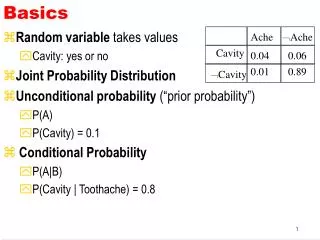
Introduction This presentation is designed to provide basic knowledge of rackmount specifications, as well as demonstrations on the installations of some of the commonly used accessories. Although we try to cover all topics related to rackmount computer chassis, please feel free to contact us should you come across anything that you might need more assistance on. The information given in the following sections is based on the EIA-RS-310 rackmount equipment specifications.
Types of Equipments Cabinet Cabinet is usually refer to a freestanding and self-supporting enclosure for housing electrical and or electronic equipment. It is usually fitted with doors and/or side panels, which may or may not be removable. A cabinet shall be standard when it conforms to the dimensional requirements. 17.72” (450mm) min Inside width 42U U=1.75” 18.3” (465mm )min Hole center to center 19” min Ear to ear outside dimension
An equipment or chassis in a typical cabinet can be mounted fix by ways of using front mounting ears plus rear supporting brackets. One can also place an equipment on angle supports or cantilever shelves as well. However, the most common way to mount rackmount computer or storage subsystems is by sliding rails. Below photo shows 20” and 26” ball bearing rails with quick-detach feature, AIC part number SR-20 (20”) and SR-26 (26”). The advantage of using slide rails is to allow unit to be easily pulled out of cabinet for maintenance. Also for heavier equipment mounting is easier with sliding rails, without having to hold on to the unit when mounting. Photo to the right shows a 1U and a 2U chassis with ball-bearing rails.
Rack Rack is generally referred to the two-post style open-frame type as opposed to the four-post enclosed cabinet design. Rack could be with or without casters. Since it has only two mounting posts, equipments are typically mounted by the front ears along, or by the center-mount brackets if the depth and weight of the chassis requires a more balanced mounting position. Cantilever shelves are also widely used. It is also referred to as Telco Rack, since it is widely used in the telecommunication industry to mount telephone relays. To the right is a photo of a 35U open frame rack with casters, AIC Part Number: RACK-35U-OP Cantilever Shelf Center Mount
Rackmount Computer Chassis People often have questions on what can be used in a rackmount computer chassis. Years ago only single-board computer (SBC) along with passive backplane were used in rackmount computer chassis. They were mostly used to control machinery(automation), acquire data, or for telecommunication applications (PBX). However, due to the coming of the Internet era, requirements to house large numbers of co-location servers drove the market to select something much more compact and easier to manage. As a result many of the desktop servers got transformed to the slim and rack mountable metal enclosures. The space required for four desktop servers can easily house 40 rackmount chassis in a cabinet. The rackmount computer chassis we are seeing today is nothing more than a desktop computer case with mounting ears and rails. Having said that, it is definitely a much tougher task trying to pack same amount of components into a slimmer environment. We will try to cover the characteristics of each size of rackmount computer chassis in the following few sections.
How to Select the Right Chassis There are three important factors that determine which chassis to use: 1)Size of the motherboard There are basically the following different standard sizes available today: 9” x 7.5” Flex ATX • Mini Flex ATX • Flex ATX • Micro ATX • ATX • Extended ATX • SSI EEB V. 3.0 • SSI MEB – 16” x 13” 12” x 9.6” ATX 7” x 7” Mini Flex ATX 9.6” 7.5” 13” 9.6” x 9.6” Micro ATX 12” x 13” Extended ATX or SSI EEB 3.0 9” 9.6” 13”
How to Select the Right Chassis – continued In general anything that’s longer than the ATX size of 12” x 9.6” will need to go into an extended chassis that’s at least 25” or more in depth. Some motherboards that are slightly longer at 10.5” will mostly likely fit in a shorter chassis at 21” of depth. As for SSI MEB standard of 16” x 13”, AIC’s RMC4L-S4520 chassis is designed specially for Tyan’s S4520 quad Xeon server board that comes in this form factor. 2) CPU Speed It’s important to know whether a single or dual CPU based motherboard is going to be used. Among the dual CPU’s, it’s also important to know whether it’s for Intel Tualatin, Xeon Prestonia, or AMD Athlon MP. Different chassis has different cooling design, especially in 1U where space is tight and fans are limited in size. The following chart demonstrates a “Thermal Scale” based on the available CPU’s on the market today. M o r e F a n s N e e d e d Celeron Tualatin Dual Tualatin Dual Xeon Dual Athlon P4 Athlon
How to Select the Right Chassis – continued When selecting the appropriate chassis for the processors, please also make sure to select recommended CPU coolers. After all, cooling cannot be done on the chassis along. 3) Capacity – expansion slots and drive bays The last question you should ask yourself is: what about expansion slots and drive bays? Typically 1U can take one expansion slot and the most two, and 2U can most likely get you two to three depending on the motherboards. When you need more than three expansions, or when all expansion slots need to be at different bus clocks and voltages, then 3U and higher where direct expansions are available will be your choice. Drive bay arrangements vary from single HDD with slim CD-ROM to sixteen hot-swappable drive bays with slim CD and FDD bays. Please make sure to always leave yourselves room to grow when selecting drive bay configurations. When choosing SCSI hot-swap option please make sure to use HDD with 80-pin SCA2 connector. For IDE hot-swap option, AIC has a patent-pending adjustable backplane design that will accommodate all brands of IDE HDD”s without using ribbon cable adapter.
How to Select the Right Chassis – Example Here is typically how the chassis selection process begin: Application Requirements - Please remember that a product always starts with application, not from the chassis or motherboard : Customer needs to build an email server for a small office of 10 people. He is looking at a dual PIII/Tualatin board from Tyan – S2518UGN with SCSI controller onboard along with two 1.13 GHz Intel Tualatin processors and 256MB memory. He will also need to run two 60GB Ultra-160 HDD’s in mirroring, one CD-ROM and FDD, and one PCI Gbit Ethernet card for bandwidth. Step 1 – check motherboard size: This is a 12”(W) x 9.6” (D) standard ATX server board. Therefore, we can use either long or short chassis. Step 2 – check CPU type: Dual Tualatin configuration does not require a whole lot of cooling efforts. Therefore, we do not need to choose chassis optimized for P4, Xeon, or Athlon processors. Step 3 – check expansions: Since customer only needs two SCSI HDD’s and one PCI expansion, we can select one 1U chassis with at least two hot-swap SCSI HDD bays and sufficient cooling for dual PIII. Conclusion - RMC1M has dual SCSI hot-swap bays, slim CD and FDD bays, and has six cooling fans, and since S2518 uses 25 degree slanted DIMM sockets cooling should not be a challenge. If customer is not comfortable with 1U chassis, the closest 2U chassis we can select is either RMC2M with 4 hot-swap bays, or RMC2N with 4 x 5.25” bays and use BR-SCA23 for hot-swap bay conversions.
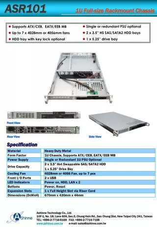
1U Chassis Basics 1U chassis is the toughest to build due to many size limitations. Although 1U is defined as 1.75”(44.45mm) high, the maximum height of the chassis is actually at around 44mm which is approximately 1.732”, leaving just about 0.45mm of clearance between every two 1U boxes. With the sheet metal thickness at 1.2mm at top and bottom, we are left with only about 1.64” of net height for everything that needs to go into this box. 41.6mm = 1.64” 44mm 1.2mm 40mm Fan As a result, the maximum height of any component that needs to fit in a 1U is at 1.6”. A full-size CD-ROM drive and a full-height HDD are all at 1.6” high. To allow better air flow, a slim CD-ROM drive and 1” HDD are usually preferred.
1U Chassis Basics- continued Also due to the height limitation, low-profile CPU coolers must be used in 1U. Preferably copper heat sink based CPU coolers are used for much needed thermal characteristics. A right-angle riser card must be used to provide expansion slot in 1U as well. 1U low-profile Copper heat sink CPU cooler AIC Part # CPU-P4-FAN
1U Chassis - Expansions 1U chassis with it’s low-profile form factor provides space-saving advantage over bigger chassis. In ISP’s co-location data center where monthly charge is based on the amount of space occupied, 1U is often the choice of many. Although cost of 1U chassis and associated components typically are higher than that of 2U and above, the monthly savings should pay for the higher initial costs in no time. The disadvantages of 1U chassis are expandability and thermal. Majority of 1U chassis can provide only one PCI expansion slot. However, AIC has many 1U chassis that can provide two expansion slots. Here is a closer look at RMC1N-XP chassis. 1 2 1 2
1U Chassis - Cooling Thermal in 1U chassis has always been an issue for many people. The newest technologies for cooling fans and blowers adopted by AIC along with some proprietary innovative designs enabled us to conquered the toughest cooling challenges to date. AIC’s patent-pending air-intake air duct along with powerful exhaust fans provide the best cooling solution on the market today.
2U Chassis Basics . As you can see 2U chassis has much more room to work with, therefore, it does not have as big of a challenge on cooling as 1U. 2U also has more expansion capabilities. 1.2mm Power supply 8CM Fan 88mm Low-profile slots without riser card 3 full-height expansions via 3-slot PCI riser card
2U Chassis – Riser Cards . Many people have questions on how to use riser card. Riser card is merely acting as an extension to the onboard PCI slots. There are basically two types of riser cards available. Active – uses PCI bridge on the riser card itself to provide IRQ signals Passive – uses paddle boards to transfer IRQ signals from other slots off the motherboard. Due to the specifications of PCI slot, each slot only carries one IRQ signal. Therefore, when putting three cards into one slot the additional two IRQ signals must be routed from other onboard PCI slots. AIC provides passive riser cards with paddle boards for cost-competitiveness reasons. Photo to the right shows RC2-017 riser card with 2 x 64-bit PCI plus AGP Pro slots. This is a “combo” card where two distinct cards are combined into one providing connections from two different sources with different bus clock and voltages.
2U Chassis – Riser Cards - continued . Determining which motherboard is suitable to use which riser card is not as difficult as many think. Below is a standard ATX motherboard from Intel – SAI2. The circled mounting hole in the picture is on every motherboard, and can be used to determine whether this board has the right slot locations for riser cards or not. 1” This mounting hole is the one immediately following the onboard I/O ports. Approximately 1” to the left of this mount hole is typically referred to as #6 or #2 slot, depending whether #1 slot is marked as the last one on the left or the one right behind this mounting hole. In either case, if this is a PCI slot you will have no problem using a standard riser card. For the case where this slot is either an AGP or missing completely, you would need to use an “offset” riser card for PCI expansion, such as RC2-011 (32-bit with ribbon bridge) or RC2-016 (64-bit with PCB bridge) riser cards. Onboard I/O ports
2U Riser Card Types Below diagrams show the three major types of riser cards that AIC offers for 2U chassis. Riser Card Mounting Plane – Cannot Change No Connection Ribbon Cable AGP Slot Extension AGP Slot IRQ Paddle Boards Basic Type- directly connected Example: RC2-007 : 32 bit x 3 RC2-012 : 64 bit x 2 Offset type Example: RC2-011 : 32 bit x 3 with ribbon RC2-016 64 bit x 2 using PCB instead of ribbon cable Dual AGP+PCI type Example: RC2-013 : 32 bit x 2 + AGP RC2-017 : 64-bit x 2 + AGP Pro
3U Chassis Basics . The significance of 3U chassis is that this form factor is the smallest one can use without using riser cards for full size PCI expansions. However, there is still a height limit of 3.9” on the expansion cards allowed due to physical limitation of 3U form factor. Not needing riser card also has another advantage, which is to allow expansions of PCI-X slots with different speeds. Some high speed AGP PRO video cards also do not work well with riser cards due to signal timing delays caused by riser cards. 1.2mm 3.9” Max 8CM Fan 132.5 mm Power supply 3U chassis also offers significantly more drive bays than 1U and 2U chassis.
4U ~ 7U Chassis 4U chassis basically is the closest to desktop computer chassis in dimensions. For that reason AIC’s RMC4S can also be configured as desktop or mid-tower computer chassis. 4U can take pretty much any desktop components, including PS/2 size power supplies and full-size CD-ROM drives. Also, 4U can take 120mm fans for high air-volume cooling. 5U is just a height-extension of 4U with one extra “U” of space for additional drive bays. The extended 5U chassis is often the popular choice for telecommunication industry with 20 slot expansions and large capacity redundant power supply options. 7U chassis is designed to use height to exchange for depth. For customer that needs the capacity 5U extended chassis offers yet has a 20” deep cabinet, 7U is the perfect choice with double-deck design.
Hot-Swap Backplane This section is designed to give some graphic illustrations on how to connect IDE and SCSI backplane. IDE – There is really no standard way to make an IDE HDD hot-swappable (or warm-swap). Since data and power on the IDE HDD comes from two different connectors, one needs to combine them to make one single hot-swappable connection. AIC uses a 48-pin connector to combine the 4-pin power with the 40-pin data connectors. Since the data connector is fixed and is located differently from brand to brand, we use a patent-pending design that allows up to 3mm of adjustable lateral space to match with any drive without using flexible ribbon cable. Hard Disk Drive Tray Mid-Plane backplane IDE HDD’s can be connected either with two devices per channel, I.e., Master + Slave, or Master only with one HDD per cable. To do hot-swap it is recommended to use only a single Master drive per cable.
IDE - continued When using a typical two-channel IDE controller or RAID controller without hot-swap, the cables are connected as follows: ATA 100 HBA or motherboard onboard controller Channel 2 Channel 1 Master 2 Slave 2 Master 1 Slave 1 This is the ideal setup for RMC1F chassis with four internal HDD bays.
IDE - continued When using a typical four-channel IDE RAID controller with hot-swap support, the cables are connected as follows: ATA 100 IDE RAID Controller RMC1Q is ideal for this kind of setup but with only three hot-swap IDE HDD’s. For RMC4D-IDE chassis user can use two 8-channel IDE RAID controllers to support sixteen Master HDD’s. It is recommended to use round cables for easier cable-routing and better air flow. Channel 1 Channel 2 Channel 3 Channel 4 Master 1 Master 2 Master 3 Master 4 RAID 0 - striping RAID 1 - Mirroring RAID 5 – striping with parity
SCSI Backplane When choosing a chassis with SCSI hot-swap bays please use SCSI HDD’s with SCA2 80-pin connector, which consists of 68-pin of data plus grounding and power. The power pins are made slightly longer, so that when disengaging the HDD from backplane, data pins would be disconnected first while power pins are still connected for split of a second. This standard design enables a safe hot-swap interface for the hard disk drives. SCSI devices can be daisy-chained, and each channel can support up to 15 devices. Therefore, when using a dual-channel controller one can select to run all the attached devices all in one single channel, or split into dual channels for mirroring or better performance. Below shows how RMC1Q-SCSI chassis can be configured with a single cable. HDD # 3 HDD # 2 HDD # 1 To HBA This configuration shows three single-bay SCSI backplane daisy-chained with one single cable with five connectors. Termination is done at the end of the cable with a female terminator. Female Terminator
SCSI Backplane-continued The following figures shows how RMC2D’s three backplanes can be connected as single channel of 9 devices or dual channels of 3 + 6 devices. HDD 7, 8, 9 HDD 4, 5, 6 HDD 1, 2, 3 OUT OUT OUT male Terminator IN IN IN Each backplane supports three HDD’s and only link cable is needed to connect every two backplane. To HBA HDD 1, 2, 3 HDD 4, 5, 6 HDD 1, 2, 3 OUT OUT OUT male Terminator male Terminator IN IN To HBA Channel 2 To HBA Channel 1
SATA Serial ATA is a new serial I/O technology that utilizes point-to-point data transmission method to get rid of the bus-arbitration and saturation bottlenecks that typical parallel I/O devices face. Therefore each HDD must be connected directly to a dedicated channel on a controller (HBA). SATA RAID Controller SATA also offers another advantage over PATA or SCSI as you can see from the figure to the left, the cable. Each SATA cable only has 7 wires as opposed to 80 in the ATA100 cable. The smaller cable makes cable-routing much easier, and thus improve the air flow in low-profile chassis such as RMC1D and 2E where high capacity drive bays are designed HDD 1 HDD 2 HDD 3 HDD 4 RAID 0 - striping RAID 1 - Mirroring RAID 5 – striping with parity