Download
1 / 14
140 likes | 363 Views
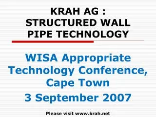
KRAH AG : STRUCTURED WALL PIPE TECHNOLOGY. WISA Appropriate Technology Conference, Cape Town 3 September 2007 Please visit www.krah.net. Who and What is Krah?. Krah AG of Germany commenced 1969 40 polyolefin pipe plants worldwide Reference list over 260 major projects

E N D
KRAH AG : STRUCTURED WALL PIPE TECHNOLOGY WISA Appropriate Technology Conference, Cape Town 3 September 2007 Please visit www.krah.net
Who and What is Krah? • Krah AG of Germany commenced 1969 • 40 polyolefin pipe plants worldwide • Reference list over 260 major projects • Structured wall - gravity pipelines (KPS) • Structured wall - pressure pipes (KPPS) • Diam 300-4000mm- 16kN/m2 or 2500kPa • Comply with applicable standards • Standard pipe designs - 129 profiles • Customised designs can be computed • APPROPRIATE for SA CONDITIONS
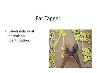
What are the Attributes? • Good hydraulics – smooth inner surface • Tough – abrasion and impact resistance • Chemical resistance – chemically inert • Inspection friendly – bright yellow liner • Safe joint – integrated electro-fusion • Flexible – will flex not fracture • Light weight – fast cheap construction • Design is a permutation of 5 attributes • 100 year life – environmentally correct • APPROPRIATE for INFRASTRUCTURE
Are the Designs and Standards Adequate? • Hydraulic design ATV-DVWK-A110E a 79 page comprehensive document Sept. 2001 • Structural design ATV-DVWK-A127E a 91 page comprehensive document Aug. 2000 • Dimensions and Technical DIN 16961-1/2 • System specification prEN 13476-1/2/3 • Design software includes all in-situ soil strength in the “soil pipe structure” • Manufacture control software integrated with design software to prevent errors. • APPROPRIATE TECHNOLOGY for SA
Design is a Permutation of Five Attributes Equivalent solid wall pipe is, eq = (Ix . 12)^1/3 w=wall thickness pd=profile width sd=core tube diameter pc=core encapsulation e=neutral axis of wall pc sd e w pd
Is It a Complete System? • Bends, branches, laterals, reducers, house connections and in-line or tangential manholes • Design software “Easy Pipe” integrated with manufacturing software “Mickey” • Complete design detail submitted to client for adjudication and approval • Electro-fusion bar code in each socket • Joint clamped; pressure + temperature • Traceability of every weld and pipe
RESULTS OF EASY PIPE DESIGNS • RUN 1: Standard Installation This is typical the in excess one that is done when data are not had on the work, assuming conditions of standard installation. • RUN 2: Very Low cover depths In this run the value of the minimum cover depths is modified, taking minimun value accepted by EASY PIPE, that is 0.5 mts. • RUN 3: Very deep cover depths In this run the value of the max. Cover depths, taking it to 7.00 is modified mts • RUN 4: Water table In this run the water table is added, to a height of 2 mts over the max. level of the seat bed. • RUN 5: Combination of all RUNS Here all the changes done in the previous runs are put into play, is to say the parameters of RUN 1 but changing: the minimum cover depth to 0.5 mts, the Maxima cover depth to 7.00 mts and 2.00 the water table level to mts over the seat bed.
CONCLUSIONS The results show that, contrary to the intuition, the annular rigidity that need the tubes for certain condition of installation he is not constant, but that will depend on the diameter of such (to see graph). This must to the different interaction tube-settles (fundamental to obtain a joint package structural) that takes place in each measurement and thus it demonstrates that the rigidity of the tube only has an intervention limited in the structural resistance of the set. Take note also how it substantially increases to the necessary rigidity before the combination of high cover depth and water table, which increases exponentially when the phreatic level rises. Please visit www.krah.net