Download
1 / 1
10 likes | 139 Views
University of . Nebraska-Lincoln. Controllable Growth of Carbon Nano -Onions for Developing High-Performance Supercapacitors. Y. Gao , Y. S. Zhou, J. Hudgins, and Y. F. Lu* Department of Electrical Engineering, University of Nebraska, Lincoln

E N D
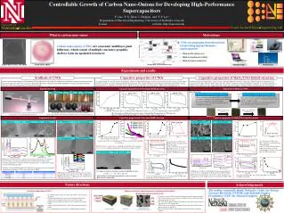
University of Nebraska-Lincoln • Controllable Growth of Carbon Nano-Onions for Developing High-Performance Supercapacitors Y. Gao, Y. S. Zhou, J. Hudgins,and Y. F. Lu* Department of Electrical Engineering, University of Nebraska, Lincoln E-mail: ylu2@unl.edu website: http://lane.unl.edu Laser Assisted Nano-Engineering Lab What is carbon nano-onion Motivations • CNOs are promising electrode material in fabricating high-performance supercapacitors Carbon nano-onions (CNOs) are concentric multilayer giant fullerenes, which consist of multiple concentric graphitic shells to form encapsulated structures Emergency doors on jet planes Hybrid auto Battleship ignition • High specific surface area • High electrochemical stability • High electronic conductivity Carbon Nano-Onion: non-edible Fresh Onion: edible Ragone plot: www.imechanica.org Backup power supply Wind energy storage Experiments and results Capacitive properties of CNOs Synthesis of CNOs Capacitive properties of MnO2/CNO hybrid structure A laser-assisted combustion process for growing CNO in open air was developed by using laser irradiations to achieve resonant excitation of precursor molecules. The laser energy was much more effectively coupled into the flame through the resonant excitation of ethylene molecules at 10.532 µm than other non-resonant wavelength. A simple method was used to activate the primitive CNOs by using KOH solution to achieve the increased specific surface areas of CNOs. Carbon materials have high SSAs, long cycle life, and high conductivity but low capacitance. Metal oxides have high theoretical capacitance but suffer from low SSAs, short cycle life, and low conductivity. Metal oxide/CNO composite is a potential approach to improve both capacitance and conductivity. In this study, capacitive properties of MnO2/CNO hybrid structure were investigated. In brief, (1) CNOs was firstly impregnated in KOH solution for 24 h; (2) The solution was filtered to get the impregnated CNOs. (3) The obtained CNOs was dried in an oven for 12 h at ~90 ℃; (4) At last, the CNOs were annealed at ~800 ℃ in N2 atmosphere for 1 h. Experiment set-up Capacitive properties of CNOs before KOH activation Deposition of MnO2 on CNOs (a) (c) Experiment steps: (d) (b) Without laser 10.333 m 10.532 m 800 W: 25 F/g 1000 W: 30 F/g 400 W: 16 F/g Deposition of MnO2 on CNO/Ni foam Electrophoretic deposition of CNOs on Ni foams • After drying, the CNO coated Ni foams were immersed into the precursor solution ( mixture of 0.1 M Na2SO4 and 0.1 M KMnO4) for MnO2 coating. • After immersing, the samples were rinsed using deionized water and then heated at 120 ℃ for 12 h in air. • CNOs were dispersed in ethanol. Al(NO3)3 was added into the solution to stabilize the CNO particles in the solution; • The suspension was ultrasonicated for 30 min; • Then a layer of CNOs was deposited onto Ni foams by electrophoretic deposition. CNOs deposited onto Ni foam MnO2 deposited onto CNO/Ni foam (a) Specific surface areas (SSAs) of CNOs grown at different laser powers. (b - d) Cyclic voltammograms of CNO electrodes. Illustration of the experimental setup for CNO growth with resonant excitation by a wavelength-tunable CO2 laser. Photographs of ethylene-oxygen flames under laser excitation (The images below show molecular vibration under the excitation conditions). • The SSAs increase with the increase in laser power. Consequently, the capacitance of CNOs increases. • However, CNOs with much larger SSAs are needed to achieve improved capacitances. Experiment results Capacitive properties of CNOs after KOH activation Capacitive properties of MnO2/CNO hybrid structure (a) (a) (a) (b) (b) (b) (a) (c) (b) (a) (b) (a) Without laser Without laser 10.532 m 10.532 µm-400 W (b) 3 h MnO2 deposition Before MnO2 deposition 10.333 m Before activation 12 h deposition Before activation 6 M activation 500 nm 500 nm 5 nm 5 nm 5 nm (d) (e) (c) (d) 12 h MnO2 deposition (c) 6 h MnO2 deposition (d) 10.532 µm-600 W G (c) D (c) 12 h deposition: 313 F/g 6 M activation: 108 F/g (a) SSAs and (b) Pore size distributions of CNOs activated at different KOH concentrations. The SSAs increase with the increase of KOH concentration. After activation, pores (<= 5 nm) contribute significantly to the total pore volume of CNOs. (a) Capacitance of CNOs after MnO2 deposition. (b) Galvanostatic charge/discharge curves of CNOs before and after 12 h MnO2 deposition. (c) Cyclic voltammograms of CNOs before and after 12 h MnO2 deposition. . (a) Capacitance of CNOs after KOH activation. (b) Galvanostatic charge/discharge curves of CNOs before and after 6 M KOH activation. (c) Cyclic voltammograms of CNOs before and after 6 M KOH activation. Before activation: 25 F/g Before activation: 25 F/g Without laser 500 nm 500 nm 10.333 m 5 nm 5 nm (c) (d) After activation Before activation 2D 10.532 m (e) (f) (e) MnO2 12 h deposition (b) (a) (a) TEM images of CNOs (c) before activation (d) after 6M activation. (b) 12 h deposition 6 h deposition TEM images of CNOs grown (a) without laser excitation and with laser excitations at (b) 10.333 and (c) 10.532 µm. (d) Raman spectra of CNOs grown without laser excitation and with laser excitations at 10.333 and 10.532 µm . (e) Typical curve fitting of a first-order Raman spectrum. 6 h deposition 3 h deposition 3 h deposition Without deposition Without deposition 5nm 5nm Summary of G-band FWHM and R3 for CNOs grown without laser excitation and with excitation at wavelengths of 10.333 and 10.532 µm at 1000 W. It is suggested that the activation of carbon with KOH proceeds as SEM images of CNOs (a) without MnO2 deposition and with (b) 3 h, (c) 6 h, (d) 12 h deposition. (e) Raman spectra of CNOs without MnO2 deposition and with (b) 3 h, (c) 6 h, (d) 12 h deposition. (f) Raman spectra of the samples in the spectra range from 200 to 1000 cm-1 . TEM images of CNOs grown (a) without laser excitation and with different laser powers of (b) 400, (c) 600, and (d) 1000 W at 10.532 µm. (e) Raman spectra of CNOs grown with different laser powers. 6KOH + C ↔ 2K +3H2 + 2K2CO3 (a) Cyclic voltammograms and (b) the capacitances of CNOs after 12 h MnO2 deposition. Then it followed by decomposition of K2CO3 and/or reaction of K/K2CO3/CO2, with carbon. (a) Cyclic voltammograms and (b) the capacitances of CNOs after 6 M KOH activation at different scan rates. Future directions Acknowledgements The authors gratefully thank Nebraska Center for Energy Sciences Research (NCESR) and National Science Foundation (NSF) for financial support. Scalable production of CNOs High-performance supercapacitors using hierarchical three-dimensional micro/nanoelectrodes • 25 welding torches with 3 mm orifice tips will be used to generate the flames. • A wavelength-tunable CO2 laser at a wavelength of 10.532 µm will be used to resonantly couple laser energy to the flame. • Another laser at 10.591 µm will be used to control the size of the CNOs. • A fume collector will be used to collect CNOs generated from the flames. • It is estimated that a production rate of 500 g/h will be achieved. • To achieve increased SSAs and reduced internal resistance at the same time; • The Ni foams will serve as conductive scaffolds to house CNTs and CNOs to reduce the matrix resistivity; • The CNTs will be grown within the Ni foams to reduce the matrix resistivity and increase the SSA significantly; • CNOs will be used to fill the remaining spacing among the Ni forms and to further increase the total SSA; • Since all CNTs and CNOs will be filled within the Ni foams, no binder is required.


![Nm]](https://cdn3.slideserve.com/6300766/slide1-dt.jpg)