Designing a Robust Frame for Quadcopter Aircraft Using ANSYS Simulations
Develop a frame for Novakinetics’ piloted quadcopter using Finite Element Analysis ANSYS simulations. Evaluate materials and dimensions for optimal frame construction. Client Redesign: Revamp FanFlyer shell design with specific specifications. Engineering, Manufacturing, and Project Budget: Implement client feedback, conduct ANSYS simulations, and manage resources efficiently. Team Roles: Assign tasks, such as ANSYS modeling and material research, to team members for successful project completion. Future Steps: Plan ANSYS simulations, solidworks redesigns, and code programs to refine the frame design. Collaboration: Select the final design, incorporating insights from team members, to meet client expectations. Continual Improvement: Enhance frame designs iteratively, considering ANSYS data and client preferences. References: Utilize reliable sources and hardware reviews to inform design decisions.

Designing a Robust Frame for Quadcopter Aircraft Using ANSYS Simulations
E N D
Presentation Transcript
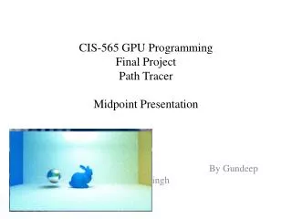
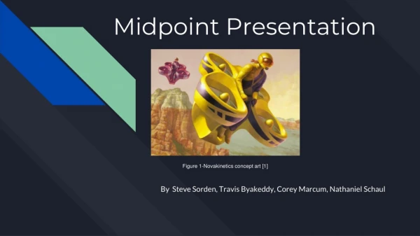
Midpoint Presentation Figure 1-Novakinetics concept art [1] By Steve Sorden, Travis Byakeddy, Corey Marcum, Nathaniel Schaul
Topic 1: Project description Design a frame for piloted quadcopter aircraft designed by Novakinetics using Finite Element Analysis ANSYS simulations and modeling. Analyze different materials and dimensions for use in the frame.
Topic 2: Design Description Client Redesign Client Original Design
FanFlyer Shell Design Back FanFlyer Bottom FanFlyer Left FanFlyer Iso FanFlyer
Topic 3: ER & Manufacturing thus far Sketches
Location of 7th requested support Top Side
Various Fixed ANSYS points Center Top Bottom All Vertical
Redesign 2 - one vs multiple fixed points Bottom Fixed point Top Fixed point Multiple Fixed Points
Recommendations • Met with Dr. Penado, ME454 professor -Closed form solutions for calculations of G-Forces. -Use ANSYS mechanical APDL 19.1 instead of ANSYS Workbench ANSYS mechanical APDL 19.1
Simple FEA Deflection Hand Calculations Deflection for 4130 Steel: 0.1547 mm Deflection for 7075-T6 Aluminum: 0.4313 mm Aluminum is 2.8 times larger
Euler’s Formula For Critical Loads [1] Critical Load Formula Critical Stress Formula
Material Testing [2] • Blue = 1 in OD, Red = 1.5 in OD, Yellow = 2 in OD • t (thickness) = 0.125 in, l (length) = 3 in • Clients choice (4130 Steel) vs Competitive choice (HT Graphite Epoxy)
Topic 4: Schedule & Budget • Budget • Client based • Schedule • Determine final design and present it to Jim Corning • On going hand calculations and ANSYS simulations for better designs
Moving Forward [2] • Travis: Perform more ANSYS simulations for each frame redesign. Continue with the proper 4130 steel properties addition to ANSYS. Continue with 3d printed force model of the Flyer, to help visualize contributions. Test ANSYS models under different approved materials. Continue with client solidworks redesigns. • Steve: Redesign frames with client and Ansys considerations, Model new frames within solidworks, assist Travis in ansys modeling of proposed frames, continue materials list and consider proposed materials to client based on research and FEA stress and deformation calculation, aid in hand calculations for FEA check, Print final proposed frame for client. • Corey: Continue hand calculations once a final frame has been designed, create working code program to test different materials under different boundary conditions, aid in designs for final proposed frame for the client, aid in ANSYS analysis of different frames. • Nathaniel: Choose a final design for our client with team.
References [1] Rigid Frames - Compression and Buckling. Note Set 11.1. 2013. Available: http://faculty-legacy.arch.tamu.edu/anichols/index_files/courses/arch614/arch614old/NS11-1frames.pdf [2] NAU FanFlyer Team. ‘Hardware Review 1,’ Flagstaff, 2019.