Wireless LANs
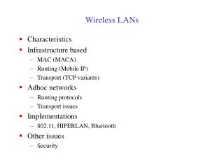
Wireless LANs. Characteristics Infrastructure based MAC (MACA) Routing (Mobile IP) Transport (TCP variants) Adhoc networks Routing protocols Transport issues Implementations 802.11, HIPERLAN, Bluetooth Other issues Security. Wireless LANs: Characteristics. Types Infrastructure based

Wireless LANs
E N D
Presentation Transcript
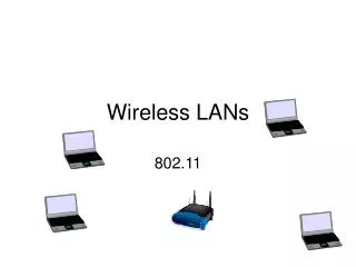
Wireless LANs • Characteristics • Infrastructure based • MAC (MACA) • Routing (Mobile IP) • Transport (TCP variants) • Adhoc networks • Routing protocols • Transport issues • Implementations • 802.11, HIPERLAN, Bluetooth • Other issues • Security
Wireless LANs: Characteristics • Types • Infrastructure based • Adhoc • Advantages • Flexible deployment • Minimal wiring difficulties • More robust against disasters (earthquake etc) • Historic buildings, conferences, trade shows,… • Disadvantages • Low bandwidth compared to wired networks (1-10 Mbit/s) • Proprietary solutions • Need to follow wireless spectrum regulations
Infrastructure vs. Adhoc Networks infrastructure network AP: Access Point AP AP wired network AP ad-hoc network Source: Schiller
Infrared uses IR diodes, diffuse light, multiple reflections (walls, furniture etc.) Advantages simple, cheap, available in many mobile devices no licenses needed simple shielding possible Disadvantages interference by sunlight, heat sources etc. many things shield or absorb IR light low bandwidth Example IrDA (Infrared Data Association) interface available everywhere Radio typically using the license free ISM band at 2.4 GHz Advantages experience from wireless WAN and mobile phones can be used coverage of larger areas possible (radio can penetrate walls, furniture etc.) Disadvantages very limited license free frequency bands shielding more difficult, interference with other electrical devices Example WaveLAN, HIPERLAN, Bluetooth Transmission: Infrared vs. Radio Source: Schiller
Wireless MAC: Motivation • Can we apply media access methods from fixed networks? • Example CSMA/CD • Carrier Sense Multiple Access with Collision Detection • send as soon as the medium is free, listen into the medium if a collision occurs (original method in IEEE 802.3) • Medium access problems in wireless networks • signal strength decreases proportional to the square of the distance • sender would apply CS and CD, but the collisions happen at the receiver • sender may not “hear” the collision, i.e., CD does not work • CS might not work, e.g. if a terminal is “hidden”
Difference Between Wired and Wireless • If both A and C sense the channel to be idle at the same time, they send at the same time. • Collision can be detected at sender in Ethernet. • Half-duplex radios in wireless cannot detect collision at sender. Ethernet LAN Wireless LAN B A B C C A
A B C Hidden Terminal Problem • Hidden terminals • A and C cannot hear each other. • A sends to B, C cannot receive A. • C wants to send to B, C senses a “free” medium (CS fails) • Collision occurs at B. • A cannot receive the collision (CD fails). • A is “hidden” for C. • Solution? • Hidden terminal is peculiar to wireless (not found in wired) • Need to sense carrier at receiver, not sender! • “virtual carrier sensing”: Sender “asks” receiver whether it can hear something. If so, behave as if channel busy.
B A D C Exposed Terminal Problem • Exposed terminals • A starts sending to B. • C senses carrier, finds medium in use and has to wait for A->B to end. • D is outside the range of A, therefore waiting is not necessary. • A and C are “exposed” terminals. • A->B and C->D transmissions can be parallel; no collisions
MACA: Multiple Access with Collision Avoidance • MACA uses signaling packets for collision avoidance • RTS (request to send) • sender request the right to send from a receiver with a short RTS packet before it sends a data packet • CTS (clear to send) • receiver grants the right to send as soon as it is ready to receive • Signaling (RTS/CTS) packets contain • sender address • receiver address • packet size • Variants of this method are used in IEEE 802.11
RTS A B C CTS CTS MACA Solutions [Karn90] • MACA avoids the problem of hidden terminals • A and C want to send to B • A sends RTS to B • B sends CTS to A • C “overhears” CTS from B • C waits for duration of A’s transmission • MACA avoids the problem of exposed terminals • B wants to send to A, C to D • C hears RTS from B->A • C does not hear CTS from A • C sends RTS to D D RTS RTS B A C D CTS
MAC: Reliability • Wireless links are prone to errors. High packet loss rate detrimental to transport-layer performance. • Solution: Use of acknowledgements • When B receives DATA from A, B sends an ACK. • If A fails to receive an ACK, A retransmits the DATA. • Both C and D remain quiet until ACK (to prevent collision of ACK). • Expected duration of transmission+ACK is included in RTS/CTS packets. • This approach adopted in many protocols [802.11]. RTS RTS A B C D CTS CTS DATA ACK • Collision of RTS/CTS packets can happen (hidden terminal). • If no CTS, retransmit RTS after backoff.
MAC: Collision Avoidance • With half-duplex radios, collision detection is not possible • Collision avoidance: Once channel becomes idle, the node waits for a randomly chosen duration before attempting to transmit • IEEE 802.11 DCF • When transmitting a packet, choose a backoff interval in the range [0,cw]; cw is contention window • Count down the backoff interval when medium is idle • Count-down is suspended if medium becomes busy • When backoff interval reaches 0, transmit RTS • Time spent counting down backoff intervals is part of MAC overhead • large cwleads to larger backoff intervals • small cw leads to larger number of collisions
B1 = 25 B1 = 5 wait data data wait B2 = 10 B2 = 20 B2 = 15 DCF Example B1 and B2 are backoff intervals at nodes 1 and 2 cw = 31
MAC: Congestion Control • Number of nodes attempting to transmit simultaneously may change with time; some mechanism to manage congestion is needed. • IEEE 802.11 DCF: Congestion control achieved by dynamically choosing the contention window cw • Binary Exponential Backoff in DCF: • When a node fails to receive CTS in response to its RTS, it increases the contention window • cw is doubled (up to a bound CWmax) • Upon successful completion data transfer, restore cw to CWmin • Optimization: MACAW • 802.11: cw reduces much faster than it increases • Backoff: multiply cwby 1.5 (instead of doubling) • Restore: Reduce cw by 1 (instead of CWmin) • cw reduces slower than it increases. Exponential increase linear decrease • Avoids wild oscillations of cw when congestion is high.
MAC: Energy Conservation • Wireless nodes need to conserve power (“resource poor”). • Typical solution: Turning the radio off when not needed • Power Saving Mode in IEEE 802.11 (Infrastructure Mode) • An Access Point periodically transmits a beacon indicating which nodes have packets waiting for them • Each power saving (PS) node wakes up periodically to receive the beacon • If a node has a packet waiting, then it sends a PS-Poll • After waiting for a backoff interval in [0,CWmin] • Access Point sends the data in response to PS-poll
MAC Protocols: Summary • Wireless medium is prone to hidden and exposed terminal problems • Protocols are typically based on CSMA/CA • RTS/CTS based signaling • Acks for reliability • Contention window is used for congestion control • IEEE 802.11 wireless LAN standard • Fairness issues are still unclear
Routing and Mobility • Finding a path from a source to a destination • Issues • Frequent route changes • amount of data transferred between route changes may be much smaller than traditional networks • Route changes may be related to host movement • Low bandwidth links • Goal of routing protocols • decrease routing-related overhead • find short routes • find “stable” routes (despite mobility)
Mobile IP (RFC 2002): Motivation • Traditional routing • based on IP destination address • network prefix determines physical subnet • change of physical subnet implies • change of IP address (conform to new subnet), or • special routing table entries to forward packets to new subnet • Changing of IP address • DNS updates take to long time • TCP connections break • security problems • Changing entries in routing tables • does not scale with the number of mobile hosts and frequent changes in the location • security problems • Solution requirements • retain same IP address, use same layer 2 protocols • authentication of registration messages, …
Mobile IP: Basic Idea Router 3 MN S Home agent Router 1 Router 2 Source: Vaidya
Mobile IP: Basic Idea move Router 3 S MN Foreign agent Home agent Router 1 Router 2 Packets are tunneled using IP in IP Source: Vaidya
Mobile IP: Terminology • Mobile Node (MN) • node that moves across networks without changing its IP address • Home Agent (HA) • host in the home network of the MN, typically a router • registers the location of the MN, tunnels IP packets to the COA • Foreign Agent (FA) • host in the current foreign network of the MN, typically a router • forwards tunneled packets to the MN, typically the default router for MN • Care-of Address (COA) • address of the current tunnel end-point for the MN (at FA or MN) • actual location of the MN from an IP point of view • Correspondent Node (CN) • host with which MN is “corresponding” (TCP connection)
Data transfer to the mobile system HA 2 MN Internet home network 3 receiver foreign network FA 1 1. Sender sends to the IP address of MN, HA intercepts packet (proxy ARP) 2. HA tunnels packet to COA, here FA, by encapsulation 3. FA forwards the packet to the MN CN sender Source: Schiller
Data transfer from the mobile system HA 1 MN Internet home network sender FA foreignnetwork 1. Sender sends to the IP address of the receiver as usual, FA works as default router CN receiver Source: Schiller
Reverse tunneling (RFC 2344) HA 2 MN Internet home network 1 sender FA foreignnetwork 1. MN sends to FA 2. FA tunnels packets to HA by encapsulation 3. HA forwards the packet to the receiver (standard case) 3 CN receiver Source: Schiller
Mobile IP: Other Issues • Reverse Tunneling • firewalls permit only “topological correct“ addresses • a packet from the MN encapsulated by the FA is now topological correct • Agent Advertisement • HA/FA periodically send advertisement messages into their physical subnets • MN listens to these messages and detects, if it is in home/foreign network • MN reads a COA from the FA advertisement messages • Registration • MN signals COA to the HA via the FA • HA acknowledges via FA to MN • limited lifetime, need to be secured by authentication • Optimizations • Triangular Routing • HA informs sender the current location of MN • Change of FA • new FA informs old FA to avoid packet loss, old FA now forwards remaining packets to new FA
Multi-Hop Wireless Networks • May need to traverse multiple links to reach destination • Mobility causes route changes Source: Vaidya
B A A B Mobile Ad Hoc Networks (MANET) • Host movement frequent • Topology change frequent • No cellular infrastructure. Multi-hop wireless links. • Data must be routed via intermediate nodes. Source: Vaidya
Routing in MANET • Mobile IP needs infrastructure • Home Agent/Foreign Agent in the fixed network • DNS, routing etc. are not designed for mobility • MANET • no default router available • “every” node also needs to be a router • Can we use traditional routing algorithms? • Distance Vector • periodic exchange of routing tables (destination, distance, next hop) • selection of the shortest path if several paths available • Link State • periodic notification about current state of physical links (flooding) • router get a complete picture of the network
Traditional Routing • A routing protocol sets up a routing table in routers • A node makes a local choice depending on global topology Source: Keshav
Distance-vector & Link-state Routing • Both assume router knows • address of each neighbor • cost of reaching each neighbor • Both allow a router to determine global routing information by talking to its neighbors • Distance vector - router knows cost to each destination • Link state - router knows entire network topology and computes shortest path
Distance Vector Routing: Example 2 Source: Keshav
Link State Routing: Example Source: Keshav
Extending Traditional Routing to MANET • Traditional routing protocols have been designed for fixed networks with infrequent changes; typically assume symmetric links • MANET • dynamic topology: • frequent route changes • no “border” routers • wireless medium: • variable connection quality • limited bandwidth (further reduced due to routing updates) • links may be asymmetric • resource poor mobile nodes: • routing table updates consume energy without contributing to data Tx • sleep modes difficult to realize
MANET Routing Protocols • Reactive protocols • Determine route if and when needed • Source initiates route discovery • Example: DSR (dynamic source routing) • Proactive protocols • Extension of traditional routing protocols • Maintain routes between every host pair at all times • Example: DSDV (destination sequenced distance vector) • Hybrid protocols • Adaptive; Combination of proactive and reactive • Example : ZRP (zone routing protocol) • Multicast routing
Dynamic Source Routing (DSR) [Johnson96] • When source S wants to send a packet to destination D, but does not know a route to D, S initiates a route discovery • S floods Route Request (RREQ) • Each node appends its own identifier when forwarding RREQ • D on receiving the first RREQ, sends a Route Reply (RREP) • RREP sent on route obtained by reversing the route appended in RREQ • RREPincludes the route from S to D, on which RREQ was received by D • S on receiving RREP, caches the route included in the RREP • When S sends a data packet to D, entire route is included in the header • Intermediate nodes use the source route in the packetheader to determine to whom a packet should be forwarded
Route Discovery in DSR Y Z S E F B C M L J A G H D K I N Represents a node that has received RREQ for D from S Source: Vaidya
Route Discovery in DSR Y Broadcast transmission Z [S] S E F B C M L J A G H D K I N Represents transmission of RREQ [X,Y] Represents list of identifiers appended to RREQ
Route Discovery in DSR Y Z S [S,E] E F B C M L J A G [S,C] H D K I N • Node H receives packet RREQ from two neighbors: • potential for collision
Route Discovery in DSR Y Z S E F [S,E,F] B C M L J A G H D K [S,C,G] I N • Node C receives RREQ from G and H, but does not forward • it again, because node C has already forwarded RREQ once
Route Discovery in DSR Y Z S E F [S,E,F,J] B C M L J A G H D K I N [S,C,G,K] • Nodes J and K both broadcast RREQ to node D • Since nodes J and K are hidden from each other, their • transmissions may collide
Route Discovery in DSR Y Z S E [S,E,F,J,M] F B C M L J A G H D K I N • Node D does not forward RREQ, because node D • is the intended targetof the route discovery
Route Reply in DSR Y Z S RREP [S,E,F,J,D] E F B C M L J A G H D K I N Represents RREP control message
Data Delivery in DSR Y Z DATA [S,E,F,J,D] S E F B C M L J A G H D K I N Packet header size grows with route length
DSR Issues • Optimizations: cache routes learnt by any means • When S finds route [S,E,F,J,D] to D, S also learns route [S,E,F] to F • When K receives RREQ[S,C,G] for G, K learns route [K,G,C,S] to S • When F forwards RREP [S,E,F,J,D], F learns route [F,J,D] to D • When E forwards Data [S,E,F,J,D], E learns route [E,F,J,D] to D • Advantages • Routes maintained only between nodes who need to communicate • Reduces overhead of route maintenance • Caching (at intermediate nodes) can further reduce route discovery overhead • Disadvantages • Packet header size grows with route length due to source routing • Flood of route requests may potentially reach all nodes in the network • Route Reply Storm problem: Many intermediate nodes reply from local cache • Stale caches will lead to increased overhead
Destination-Sequenced Distance-Vector (DSDV) [Perkins94Sigcomm] • Each node maintains a routing table which stores • next hop, cost metric towards each destination • a sequence number that is created by the destination itself • Each node periodically forwards routing table to neighbors • Each node increments and appends its sequence number when sending its local routing table • Each route is tagged with a sequence number; routes with greater sequence numbers are preferred • Each node advertises a monotonically increasing even sequence number for itself • When a node decides that a route is broken, it increments the sequence number of the route and advertises it with infinite metric • Destination advertises new sequence number
Destination-Sequenced Distance-Vector (DSDV) • When X receives information from Y about a route to Z • Let destination sequence number for Z at X be S(X), S(Y) is sent from Y • If S(X) > S(Y), then X ignores the routing information received from Y • If S(X) = S(Y), and cost of going through Y is smaller than the route known to X, then X sets Y as the next hop to Z • If S(X) < S(Y), then X sets Y as the next hop to Z, and S(X) is updated to equal S(Y) Z X Y
Reactive v/s Proactive Trade-offs • Reactive protocols • Lower overhead since routes are determined on demand • Significant delay in route determination • Employ flooding (global search) • Control traffic may be bursty • Proactive protocols • Always maintain routes • Little or no delay for route determination • Consume bandwidth to keep routes up-to-date • Maintain routes which may never be used • Which approach achieves a better trade-off depends on the traffic and mobility patterns
Zone Routing Protocol (ZRP) [Haas98] • ZRP combines proactive and reactive approaches • All nodes within hop distance at most d from a node X are said to be in the routing zone of node X • All nodes at hop distance exactly d are said to be peripheral nodes of node X’s routing zone • Intra-zone routing: Proactively maintain routes to all nodes within the source node’s own zone. • Inter-zone routing: Use an on-demand protocol (similar to DSR or AODV) to determine routes to outside zone.
ZRP: Example Radius of routing zone = 2
MANET Routing: Summary • Protocols • Typically divided into proactive, reactive and hybrid • Plenty of other routing protocols: location-aided, power-aware, …. • Several recent proposal in IETF’s MANET Working Group http://www.ietf.org/ • Performance Studies • Typically studied by simulations using ns, discrete event simulator • Nodes (10-30) remains stationary for pause time seconds (0-900s) and then move to a random destination (1500m X300m space) at a uniform speed (0-20m/s). CBR traffic sources (4-30 packets/sec, 64-1024 bytes/packet) • Attempt to estimate latency of route discovery, routing overhead … • Actual trade-off depends a lot on traffic and mobility patterns • Higher traffic diversity (more source-destination pairs) increases overhead in on-demand protocols • Higher mobility will always increase overhead in all protocols See Nitin Vaidya’s MobiCom’2000 tutorial