Download
1 / 75
750 likes | 836 Views
Explore Wireless LAN technology including IEEE802.11 applications, LAN extension, nomadic access, and ad hoc networking. Learn about requirements, categories, strengths, and drawbacks of Infrared and Spread Spectrum LANs.

E N D
Wireless LANs (IEEE802.1) Lecture 5 G. Noubir noubir@ccs.neu.edu Textbook: chapters 13, 14 Slides partially from “Mobile Communications” by J. Schiller Chapter 7.
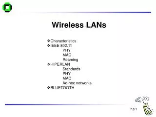
Outline • Wireless LAN Technology • Medium Access Control for Wireless • IEEE802.11
Wireless LAN Applications • LAN Extension • Cross-building interconnect • Nomadic Access • Ad hoc networking
LAN Extension • Wireless LAN linked into a wired LAN on same premises • Wired LAN • Backbone • Support servers and stationary workstations • Wireless LAN • Stations in large open areas • Manufacturing plants, stock exchange trading floors, and warehouses
Cross-Building Interconnect • Connect LANs in nearby buildings • Wired or wireless LANs • Point-to-point wireless link is used • Devices connected are typically bridges or routers
Nomadic Access • Wireless link between LAN hub and mobile data terminal equipped with antenna • Laptop computer or notepad computer • Uses: • Transfer data from portable computer to office server • Extended environment such as campus
Ad Hoc Networking • Temporary peer-to-peer network set up to meet immediate need • Example: • Group of employees with laptops convene for a meeting; employees link computers in a temporary network for duration of meeting
Wireless LAN Requirements • Throughput • Number of nodes • Connection to backbone LAN • Service area • Battery power consumption • Transmission robustness and security • Collocated network operation • License-free operation • Handoff/roaming • Dynamic configuration
Wireless LAN Categories • Infrared (IR) LANs • Spread spectrum LANs • Narrowband microwave
Strengths of Infrared Over Microwave Radio • Spectrum for infrared virtually unlimited • Possibility of high data rates • Infrared spectrum unregulated • Equipment inexpensive and simple • Reflected by light-colored objects • Ceiling reflection for entire room coverage • Doesn’t penetrate walls • More easily secured against eavesdropping • Less interference between different rooms
Drawbacks of Infrared Medium • Indoor environments experience infrared background radiation • Sunlight and indoor lighting • Ambient radiation appears as noise in an infrared receiver • Transmitters of higher power required • Limited by concerns of eye safety and excessive power consumption • Limits range
IR Data Transmission Techniques • Directed Beam Infrared • Ominidirectional • Diffused
Directed Beam Infrared • Used to create point-to-point links • Range depends on emitted power and degree of focusing • Focused IR data link can have range of kilometers • Cross-building interconnect between bridges or routers
Ominidirectional • Single base station within line of sight of all other stations on LAN • Station typically mounted on ceiling • Base station acts as a multiport repeater • Ceiling transmitter broadcasts signal received by IR transceivers • IR transceivers transmit with directional beam aimed at ceiling base unit
Diffused • All IR transmitters focused and aimed at a point on diffusely reflecting ceiling • IR radiation strikes ceiling • Reradiated omnidirectionally • Picked up by all receivers
Spread Spectrum LAN Configuration • Multiple-cell arrangement • Within a cell, either peer-to-peer or hub • Peer-to-peer topology • No hub • Access controlled with MAC algorithm • CSMA • Appropriate for ad hoc LANs
Spread Spectrum LAN Configuration • Hub topology • Mounted on the ceiling and connected to backbone • May control access • May act as multiport repeater • Automatic handoff of mobile stations • Stations in cell either: • Transmit to / receive from hub only • Broadcast using omnidirectional antenna
Narrowband Microwave LANs • Use of a microwave radio frequency band for signal transmission • Relatively narrow bandwidth • Licensed • Unlicensed
Licensed Narrowband RF • Licensed within specific geographic areas to avoid potential interference • Motorola - 600 licenses in 18-GHz range • Covers all metropolitan areas • Can assure that independent LANs in nearby locations don’t interfere • Encrypted transmissions prevent eavesdropping
Unlicensed Narrowband RF • RadioLAN introduced narrowband wireless LAN in 1995 • Uses unlicensed ISM spectrum • Used at low power (0.5 watts or less) • Operates at 10 Mbps in the 5.8-GHz band • Range = 50 m to 100 m
Motivation for Wireless MAC • Can we apply media access methods from fixed networks? • Example CSMA/CD • Carrier Sense Multiple Access with Collision Detection • send as soon as the medium is free, listen into the medium if a collision occurs (original method in IEEE 802.3) • Problems in wireless networks • signal strength decreases proportional to the square of the distance • the sender would apply CS and CD, but the collisions happen at the receiver • it might be the case that a sender cannot “hear” the collision, i.e., CD does not work • furthermore, CS might not work if, e.g., a terminal is “hidden”
Motivation - hidden and exposed terminals • Hidden terminals • A sends to B, C cannot receive A • C wants to send to B, C senses a “free” medium (CS fails) • collision at B, A cannot receive the collision (CD fails) • A is “hidden” for C • Exposed terminals • B sends to A, C wants to send to another terminal (not A or B) • C has to wait, CS signals a medium in use • but A is outside the radio range of C, therefore waiting is not necessary • C is “exposed” to B A B C
Motivation - near and far terminals • Terminals A and B send, C receives • signal strength decreases proportional to the square of the distance • the signal of terminal B therefore drowns out A’s signal • C cannot receive A • If C for example was an arbiter for sending rights, terminal B would drown out terminal A already on the physical layer • Also severe problem for CDMA-networks - precise power control needed! A B C
Access methods SDMA/FDMA/TDMA • SDMA (Space Division Multiple Access) • segment space into sectors, use directed antennas • cell structure • FDMA (Frequency Division Multiple Access) • assign a certain frequency to a transmission channel between a sender and a receiver • permanent (e.g., radio broadcast), slow hopping (e.g., GSM), fast hopping (FHSS, Frequency Hopping Spread Spectrum) • TDMA (Time Division Multiple Access) • assign the fixed sending frequency to a transmission channel between a sender and a receiver for a certain amount of time • The multiplexing schemes are now used to control medium access!
FDD/FDMA - general scheme, example GSM f 960 MHz 124 200 kHz 935.2 MHz 1 20 MHz 915 MHz 124 890.2 MHz 1 t
TDD/TDMA - general scheme, example DECT 417 µs 1 2 3 11 12 1 2 3 11 12 t downlink uplink
Frequency Division Multiple Access • Concept: • assign different frequency bands to different users • no sharing of a frequency band between two users • user separation using band-pass filters • continuous flow • two-way: two frequency bands or Time Division Duplex (TDD) • Advantages: simple receivers • longer symbol duration: no-need for equalization • low inter-symbol interference • e.g., 50kb/s QPSK =>40s >> 1-10s delay spread • Drawbacks: • frequency guard bands, costly tight RF band-filters, • long fading duration: need slow frequency hopping • may need spatial diversity (multiple antennas/beam forming) Rx/Tx
Frequency Selection • Frequency management: • Fixed (cellular phones-base stations): reuse factor • On demand (cellular phones-mobile terminals) • Dynamic (cordless/WLAN): based on sensing interference levels • Problems: congestion management, dynamic load, … • Antenna implications: • High antennas (e.g., 50m): higher coverage but higher interference between base stations (need for synchronization) • Low antennas: higher attenuation, lower coverage, better reuse • Conclusion: • Pure FDMA is only interesting for simple cordless systems (CT-2)
Time Division Multiple Access • Concept: • use the same frequency over non-overlapping periods of time • Advantages: • simple filters (window) • transmit and receive over the same frequency channel • Drawbacks: • users must be synchronized with BS (master clock over a BCH) • guard times: common 30-50s, may be less in recent systems • short symbol duration: need for equalization, training sequences... • high inter-symbol interference • e.g., 50Kbps, QPSK, 8 users: • 5 s symbol duration • delay spread: 1s (cordless), upto 20s for cellular
FDMA/TDMA • First channel allocation: • random access channel (RACH) to send short requests • ALOHA type protocol over the RACH • One can use both FDMA and TDMA • examples: GSM system, D-AMPS Frequency M9 M9 M5 M6 M5 M6 M1 M2 M3 M4 M1 M2 M3 M4 Time cycle
Access method CDMA • CDMA (Code Division Multiple Access) • all terminals send on the same frequency probably at the same time and can use the whole bandwidth of the transmission channel • codes generate signals with “good-correlation” properties • signals from another user appear as “noise” (use spread spectrum technology) • signals are spread over a wideband using pseudo-noise sequences (e.g., each sender has a unique random number, the sender XORs the signal with this random number) • the receiver can “tune” into this signal if it knows the pseudo random number, tuning is done via a correlation function • Disadvantages: • higher complexity of a receiver (receiver cannot just listen into the medium and start receiving if there is a signal) • all signals should have the same strength at a receiver (near-far effect) • Advantages: • all terminals can use the same frequency => no planning needed; macrodiversity • huge code space (e.g. 232) compared to frequency space
Aloha/slotted aloha • Mechanism • random, distributed (no central arbiter), time-multiplex • Slotted Aloha additionally uses time-slots, sending must always start at slot boundaries • Aloha • Slotted Aloha collision sender A sender B sender C t collision sender A sender B sender C t
Carrier Sense Protocols Use the fact that in some networks you can sense the medium to check whether it is currently free • 1-persistent CSMA • non-persistent CSMA • p-persistent protocol • CSMA with collision Detection (CSMA/CD): not applicable to wireless systems • 1-persistent CSMA • when a station has a packet: • it waits until the medium is free to transmit the packet • if a collision occurs, the station waits a random amount of time • first transmission results in a collision if several stations are waiting for the channel
Carrier Sense Protocols (Cont’d) • non-persistent CSMA • when a station has a packet: • if the medium is free, transmit the packet • otherwise wait for a random period of time and repeat the algorithm • higher delays, but better performance than pure ALOHA • p-persistent protocol • when a station has a packet wait until the medium is free: • transmit the packet with probability p • wait for next slot with probability 1-p • better throughput than other schemes but higher delay • CSMA with collision Detection (CSMA/CD) • stations abort their transmission when they detect a collision • e.g., Ethernet, IEEE802.3 but not applicable to wireless systems
DAMA - Demand Assigned Multiple Access • Channel efficiency only 18% for Aloha, 36% for Slotted Aloha (assuming Poisson distribution for packet arrival and packet length) • Reservation can increase efficiency to 80% • a sender reserves a future time-slot • sending within this reserved time-slot is possible without collision • reservation also causes higher delays • typical scheme for satellite links • Examples for reservation algorithms: • Explicit Reservation according to Roberts (Reservation-ALOHA) • Implicit Reservation (PRMA) • Reservation-TDMA
Access method DAMA: Explicit Reservation • Explicit Reservation (Reservation Aloha): • two modes: • ALOHA mode for reservation:competition for small reservation slots, collisions possible • reserved mode for data transmission within successful reserved slots (no collisions possible) • it is important for all stations to keep the reservation list consistent at any point in time and, therefore, all stations have to synchronize from time to time collision t Aloha reserved Aloha reserved Aloha reserved Aloha
Access method DAMA: PRMA • Implicit reservation (PRMA - Packet Reservation MA): • a certain number of slots form a frame, frames are repeated • stations compete for empty slots according to the slotted aloha principle • once a station reserves a slot successfully, this slot is automatically assigned to this station in all following frames as long as the station has data to send • competition for this slots starts again as soon as the slot was empty in the last frame reservation 1 2 3 4 5 6 7 8 time-slot ACDABA-F frame1 A C D A B A F ACDABA-F frame2 A C A B A AC-ABAF- collision at reservation attempts frame3 A B A F A---BAFD frame4 A B A F D ACEEBAFD frame5 A C E E B A F D t
Access method DAMA: Reservation-TDMA • Reservation Time Division Multiple Access • every frame consists of N mini-slots and x data-slots • every station has its own mini-slot and can reserve up to k data-slots using this mini-slot (i.e. x = N * k). • other stations can send data in unused data-slots according to a round-robin sending scheme (best-effort traffic) e.g. N=6, k=2 N * k data-slots N mini-slots reservationsfor data-slots other stations can use free data-slots based on a round-robin scheme
MACA - collision avoidance • MACA (Multiple Access with Collision Avoidance) uses short signaling packets for collision avoidance • RTS (request to send): a sender request the right to send from a receiver with a short RTS packet before it sends a data packet • CTS (clear to send): the receiver grants the right to send as soon as it is ready to receive • Signaling packets contain • sender address • receiver address • packet size • Variants of this method can be found in IEEE802.11 as DFWMAC (Distributed Foundation Wireless MAC)
A A C C MACA examples • MACA avoids the problem of hidden terminals • A and C want to send to B • A sends RTS first • C waits after receiving CTS from B • MACA avoids the problem of exposed terminals • B wants to send to A, C to another terminal • now C does not have to wait for it cannot receive CTS from A RTS CTS CTS B RTS RTS CTS B
MACA variant: DFWMAC in IEEE802.11 sender receiver idle idle packet ready to send; RTS RTS; CTS data; ACK RxBusy time-out; RTS wait for the right to send time-out data; NAK ACK time-out NAK; RTS CTS; data wait for data wait for ACK RTS; RxBusy ACK: positive acknowledgement NAK: negative acknowledgement RxBusy: receiver busy
Polling mechanisms • If one terminal can be heard by all others, this “central” terminal (a.k.a. base station) can poll all other terminals according to a certain scheme • now all schemes known from fixed networks can be used (typical mainframe - terminal scenario) • Example: Randomly Addressed Polling • base station signals readiness to all mobile terminals • terminals ready to send can now transmit a random number without collision with the help of CDMA or FDMA (the random number can be seen as dynamic address) or with collisions (over the Random Access CHannel) • the base station now chooses one address for polling from the list of all random numbers (collision if two terminals choose the same address) • the base station acknowledges correct packets and continues polling the next terminal • this cycle starts again after polling all terminals of the list
ISMA (Inhibit Sense Multiple Access) • Current state of the medium is signaled via a “busy tone” • the base station signals on the downlink (base station to terminals) if the medium is free or not • terminals must not send if the medium is busy • terminals can access the medium as soon as the busy tone stops • the base station signals collisions and successful transmissions via the busy tone and acknowledgements, respectively (media access is not coordinated within this approach) • mechanism used, e.g., for CDPD (USA, integrated into AMPS)
Protocol Throughput Pure-ALOHA S = Ge-2G Slotted-ALOHA S = Ge-G Non slotted 1-persistent Slotted 1-persistent CSMA Nonpersistent non slotted CSMA Nonpersistent slotted CSMA Throughputs of Some Random Access Protocols G: load (includes both successful transmissions and retransmissions) S: successful transmission a: ratio of propagation delay to the packet transmission delay
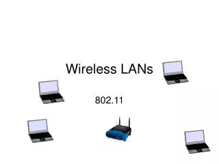
infrastructure network AP: Access Point AP AP wired network AP ad-hoc network IEEE802.11
802.11 LAN 802.x LAN STA1 BSS1 Access Point Portal Distribution System Access Point ESS BSS2 STA2 STA3 802.11 LAN 802.11 - Architecture of an infrastructure network • Station (STA) • terminal with access mechanisms to the wireless medium and radio contact to the access point • Basic Service Set (BSS) • group of stations using the same radio frequency • Access Point • station integrated into the wireless LAN and the distribution system • Portal • bridge to other (wired) networks • Distribution System • interconnection network to form one logical network (EES: Extended Service Set) based on several BSS
802.11 - Architecture of an ad-hoc network 802.11 LAN • Direct communication within a limited range • Station (STA):terminal with access mechanisms to the wireless medium • Basic Service Set (BSS):group of stations using the same radio frequency STA1 STA3 BSS1 STA2 BSS2 STA5 STA4 802.11 LAN