Download
1 / 36
360 likes | 383 Views
Learn about the importance of processing signals, both analog and digital. Explore topics such as spectrum analysis, signal filtering, and operations on sequences. Understand the different structures for implementing IIR and FIR filters.

E N D
Review: Spectrum Analysis and Digital Filter Design Gao Xinbo Dept. of E.E., School of E.E. Xidian University
Why signals should be processed? • Signals are carriers of information • Useful and unwanted • Extracting, enhancing, storing and transmitting the useful information • How signals are being processed?--- • Analog Signal Processing vs. • Digital Signal Processing
The framework of DSP PrF: antialiasing filtering PoF: smooth out the staircase waveform
Comparison of DSP over ASP -Advantages • Developed Using Software on Computer; • Working Extremely Stable; • Easily Modified in Real Time ; • Low Cost and Portable; -Disadvantages • Lower Speed and Lower Frequency
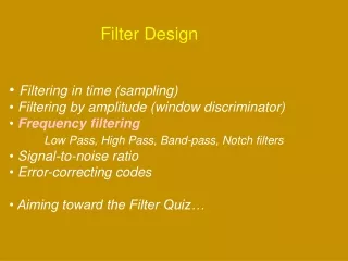
The two categories of DSP Tasks • Signal Analysis: • Measurement of signal properties • Spectrum(frequency/phase) analysis • Target detection, verification, recognition • Signal Filtering • Signal-in-signal-out, filter • Removal of noise/interference • Separation of frequency bands
Discrete-Time Signals • Unit sample sequence • Unit step sequence • Real-valued exponential sequence • Complex-valued exponential sequence • Sinusoidal sequence • Random sequence • Periodic sequence
Operations on Sequences • Signal addition • Signal multiplication • Scaling • Shifting • Folding • Sample summation • Sample production
LTI system • Principle of superposition • Linear convolution • Stability • Causality • Difference equation
系统的表述 (离散系统) • 状态方程模型 • (参数矩阵A,B,C,D) • 传递函数模型 • (参数数组 a,b) • 零极增益模型 • (参数数组 z,p,k) • 极点留数模型 • (参数数组 r,p) • 二阶串接模型 (参数矩阵 [b0k,b1k,b2k,1,a1k,a2k])
连续系统和离散系统之间的转换函数模拟/数字滤波器转换连续系统和离散系统之间的转换函数模拟/数字滤波器转换 • 1。双线性变换函数 bilinear [NUMd,DENd] = bilinear(NUM,DEN,Fs) H(z) = H(s) | | s = 2*Fs*(z-1)/(z+1) 2。脉冲响应不变法impinvar [BZ,AZ] = impinvar(B,A,Fs)
DTFT, ZT, DFT The dashed paths exist only if the system is stable
The analog and digital frequencies Fs: the sampling frequency, sam/sec • Amplitude scaled factor: 1/Ts; • Frequency-scaled factor: ω=ΩTs (ω=0~2π) • Frequency-translated factor: 2πk/Ts;
Stability and Causality • Theorem 2 z-domain LTI stability • An LTI system is stable if and only if the unit circle is in the ROC of H(z) • Theorem 3 z-domain causal LTI stability • A causal LTI system is stable if and only if the system function H(z) has all its poles inside the unit circle.
Linear convolution using the DFT In general, the circular convolution is an aliased version of the linear convolution. If we make both x1(n) and x2(n) N=N1+N2-1 point sequences by padding an appropriate number of zeros, then the circular convolution is identical to the linear convolution.
Sampling Theorem • Sampling in time-domain • Sampling in frequency-domain • Reconstruction: Interpolation
Filter Structures • The system function of an IIR filter is given by The order of such an IIR filter is called N if aN~=0. The difference equation representation of an IIR filter is expressed as
Three different structures can be used to implement an IIR filter: • Direct form • In this form, there are two parts to this filter, the moving average part and the recursive part (or the numerator and denominator parts) • Two version: direct form I and direct form II • Cascade form • The system function H(z) is factored into smaller second-order sections, called biquads. H(z) is then represented as a product of these biquads. • Each biquad is implemented in a direct form, and the entire system function is implemented as a cascade of biquad sections. • Parallel form • H(z) is represented as a sum of smaller second-order sections. • Each section is again implemented in a direct form. • The entire system function is implemented as a parallel network of sections.
FIR Filter Structure • Linear-phase form • For frequency-selective filters (e.g., lowpass filters) it is generally desirable to have a phase response that is a linear function of frequency. That is • For a causal FIR filter with impulse over [0,M-1] interval, the linear-phase conditions Symmetric impulse response vs. antisymmetric impulse response
Linear-phase form • Consider the difference equation with a symmetric impulse response. • Figure 6.12: M=7(odd) and M=6(even) • Matlab implementation • The linear-phase structure is essentially a direct form draw differently to save on multiplications. Hence in a Matlab implementation the linear-phase structure is equivalent to the direct form.
Advantages of a linear-phase response • Design problem contains only real arithmetic and not complex arithmetic; • Linear-phase filter provide no delay distortion and only a fixed amount of delay; • For the filter of length M (or order M-1) the number of operations are of the order of M/2 as we discussed in the linear phase implementation.
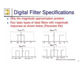
Frequency Response H(ejw) • When the case of symmetry and anti-symmetry are combined with odd and even M, we obtain four types of linear phase FIR filters. Frequency response functions for each of these types have some peculiar expressions and shapes. To study these response, we write H(ejw) as Hr(ejw) is an amplitude response function and not a magnitude response function. The phase response associated with the magnitude response is a discontinuous function, while that associated with the amplitude response is a continuous linear function.
Windows Design Techniques • Basic idea: choose a proper ideal frequency-selective filter (which always has a noncausal, infinite-duration impulse response) and then truncate (or window) its impulse response to obtain a linear-phase and causal FIR filter. • Appropriate windowing function • Appropriate ideal filter • An ideal LPF of bandwidth wc<pi is given by Where wc is also called the cutoff frequency, alpha is called the sample delay
Windows Design Techniques Note that hd(n) is symmetric with respect to alpha, a fact useful for linear-phase FIR filter. To obtain a causal and linear-phase FIR filter h(n) of length M, we must have This operation is called “windowing”.
Basic Window Design Idea • For the given filter specifications choose the filter length M and a window function w(n) for the narrowest main lobe width and the smallest side lobe attenuation possible. • From the observation 4 above we note that the passband tolerance delta1 and the stopband tolerance delta2 can not be specified independently. We generally take care of delta2 alone, which results in delta2 = delta1.
滤波器阶数(长度)M的选择 取Kaiser窗时设定beta,再用kaiserord函数求得M
Two approaches for IIR filter Approach 1, used in Matlab Approach 2, study
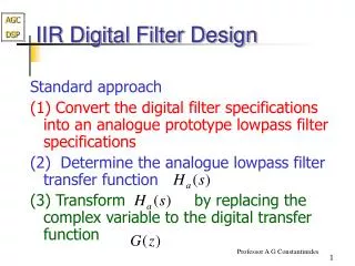
IIR Filter Design Steps • Design analog lowpass filter • Study and apply filter transformations to obtain digital lowpass filter • Study and apply frequency-band transformations to obtain other digital filters from digital lowpass filter
FIR滤波器的设计 FIR滤波器的特点: (1)线性相位,波形失真小; (2)极点在z-平面原点,必稳定; (3)易于实现
窗函数法 定预期频率特性: 通带幅频特性为1,相位线性;1*exp(-a*w) 阻带幅频特性为0;过渡带宽 由预期特性求预期脉冲响应hd 把脉冲响应与窗函数相乘,得实际的有限长度的h; h就是FIR滤波器分子系数,可用freqz函数验算其幅频特性
滤波器的设计指标 • 类型和理想特性 • Wn=[wc1,wc2,…]处的理想幅特性 • A=[A1,A2,…] • 各段允许误差Rp,As,(或delta1,delta2)
名称 近似过渡带宽 精确过渡带宽 最小阻带衰减 矩形 4π/M 1.8π/M 21dB 巴特利特 8π/M 6.1π/M 25dB 汉宁 8π/M 6.2π/M 44dB 哈明 8π/M 6.6π/M 51dB 布莱克曼 12π/M 11/M 74dB 取Kaiser窗时用MATLAB中的kaiserord函数来得到长度M 根据过渡带宽选择FIR滤波器窗函数类型和长度M的公式
FIR滤波器的其他设计方法 (二)频率抽样法 朴素算法: 等波动方法(用remez函数) (三)约束最小二乘法(fircls) 约束指的对波动的上限有规定 均方误差最小化准则 最大误差最小化准则
IIR滤波器设计步骤(用书上的方法和函数) 1。用buttap+求阶次N的公式→函数afd_butt 设计模拟低通原型; 数字指标:wp,ws,Rp,As先换成模拟指标 用双线性变换时wp,ws用预崎变变换 2。用变换函数bilinear或impinvar将模拟低通原型变换为数字低通 3。用zmapping函数将数字低通变换为数字高通、带通或带阻滤波器
That’s all! Thanks for your cooperation!