Download
1 / 28
330 likes | 685 Views
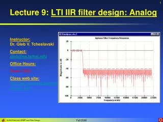
IIR Digital Filter Design. Standard approach (1) Convert the digital filter specifications into an analogue prototype lowpass filter specifications (2) Determine the analogue lowpass filter transfer function

E N D
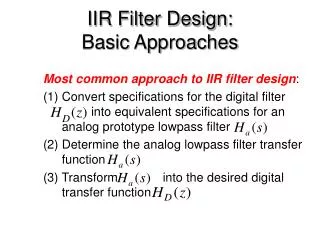
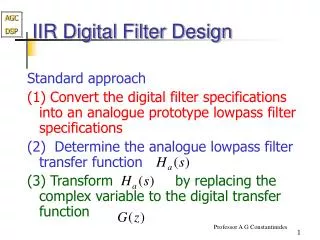
IIR Digital Filter Design Standard approach (1) Convert the digital filter specifications into an analogue prototype lowpass filter specifications (2) Determine the analogue lowpass filter transfer function (3) Transform by replacing the complex variable to the digital transfer function
IIR Digital Filter Design • This approach has been widely used for the following reasons: (1) Analogue approximation techniques are highly advanced (2) They usually yield closed-form solutions (3) Extensive tables are available for analogue filter design (4) Very often applications require digital simulation of analogue systems
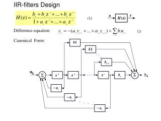
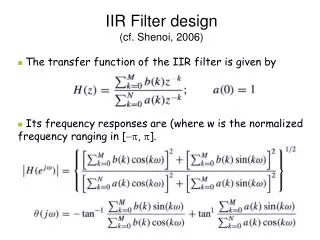
IIR Digital Filter Design • Let an analogue transfer function be where the subscript “a” indicates the analogue domain • A digital transfer function derived from this is denoted as
IIR Digital Filter Design • Basic idea behind the conversion of into is to apply a mapping from the s-domain to the z-domain so that essential properties of the analogue frequency response are preserved • Thus mapping function should be such that • Imaginary ( ) axis in the s-plane be mapped onto the unit circle of the z-plane • A stable analogue transfer function be mapped into a stable digital transfer function
IIR Digital Filter: The bilinear transformation • To obtain G(z) replace s by f(z) in H(s) • Start with requirements on G(z)
IIR Digital Filter • Hence is real and rational in z of order one • i.e. • For LP to LP transformation we require • Thus
IIR Digital Filter • The quantity is fixed from • ie on • Or • and
Bilinear Transformation • Transformation is unaffected by scaling. Consider inverse transformation with scale factor equal to unity • For • and so
Bilinear Transformation • Mapping of s-plane into the z-plane
Bilinear Transformation • For with unity scalar we have or
Bilinear Transformation • Mapping is highly nonlinear • Complete negative imaginary axis in the s-plane from to is mapped into the lower half of the unit circle in the z-plane from to • Complete positive imaginary axis in the s-plane from to is mapped into the upper half of the unit circle in the z-plane from to
Bilinear Transformation • Nonlinear mapping introduces a distortion in the frequency axis called frequency warping • Effect of warping shown below
Spectral Transformations • To transform a given lowpass transfer function to another transfer function that may be a lowpass, highpass, bandpass or bandstop filter (solutions given by Constantinides) • has been used to denote the unit delay in the prototype lowpass filter and to denote the unit delay in the transformed filter to avoid confusion
Spectral Transformations • Unit circles in z- and -planes defined by , • Transformation from z-domain to -domain given by • Then
Spectral Transformations • From , thus , hence • Therefore must be a stable allpass function
Lowpass-to-Lowpass Spectral Transformation • To transform a lowpass filter with a cutoff frequency to another lowpass filter with a cutoff frequency , the transformation is • On the unit circle we have which yields
Lowpass-to-Lowpass Spectral Transformation • Solving we get • Example - Consider the lowpass digital filter which has a passband from dc to with a 0.5 dB ripple • Redesign the above filter to move the passband edge to
Lowpass-to-Lowpass Spectral Transformation • Here • Hence, the desired lowpass transfer function is
Lowpass-to-Lowpass Spectral Transformation • The lowpass-to-lowpass transformation can also be used as highpass-to-highpass, bandpass-to-bandpass and bandstop-to-bandstop transformations
Lowpass-to-Highpass Spectral Transformation • Desired transformation • The transformation parameter is given by where is the cutoff frequency of the lowpass filter and is the cutoff frequency of the desired highpass filter
Lowpass-to-Highpass Spectral Transformation • Example - Transform the lowpass filter • with a passband edge at to a highpass filter with a passband edge at • Here • The desired transformation is
Lowpass-to-Highpass Spectral Transformation • The desired highpass filter is
Lowpass-to-Highpass Spectral Transformation • The lowpass-to-highpass transformation can also be used to transform a highpass filter with a cutoff at to a lowpass filter with a cutoff at • and transform a bandpass filter with a center frequency at to a bandstop filter with a center frequency at
Lowpass-to-Bandpass Spectral Transformation • Desired transformation
Lowpass-to-Bandpass Spectral Transformation • The parameters and are given by where is the cutoff frequency of the lowpass filter, and and are the desired upper and lower cutoff frequencies of the bandpass filter
Lowpass-to-Bandpass Spectral Transformation • Special Case - The transformation can be simplified if • Then the transformation reduces to where with denoting the desired center frequency of the bandpass filter
Lowpass-to-Bandstop Spectral Transformation • Desired transformation
Lowpass-to-Bandstop Spectral Transformation • The parameters and are given by where is the cutoff frequency of the lowpass filter, and and are the desired upper and lower cutoff frequencies of the bandstop filter