Download
1 / 38
390 likes | 719 Views
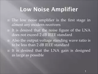
Low Noise Amplifier. The low noise amplifier is the first stage in almost any modern receivers It is desired that the noise figure of the LNA does not exceed 2 dB IEEE standard Also the output voltage standing wave ratio is to be less than 2 dB IEEE standard

E N D
Low Noise Amplifier The low noise amplifier is the first stage in almost any modern receivers It is desired that the noise figure of the LNA does not exceed 2 dB IEEE standard Also the output voltage standing wave ratio is to be less than 2 dB IEEE standard It is desired that the LNA gain is designed as large as possible
Low Noise Amplifier Three factors are considered when designing the LNA Stability The available power gain The noise figure Microwave LNA the design relies on the S-parameters of the transistor The noise model is taken into account by measuring the optimum noise resistance Rn which generates the minimum noise figure
Low Noise Amplifier Of course Rn is both bias and frequency dependent Transistor manufacturers provide Rn at different frequency points at specified bias points on their data sheet If Rn is not provided transistor characterization can be made to determine Rn Rn can be determined from Where en and in are the input voltage and the input current of the transistor
Low Noise Amplifier Consider the amplifier circuit shown below
Low Noise Amplifier As it can be seen that, the amplifier circuit is composed from input matching network, transistor and the output matching network When designing the amplifier the input and output matching reflection coefficients can be varied to achieve a certain gain, noise figure and voltage standing wave ratio Before beginning the design the stability of the amplifier must be checked first
Stability considerations The stability of an amplifier, or its resistance to oscillate is the first step in the design The stability can be determined from the S-parameters, input and output matching networks In a two port network oscillations are possible when either the input or output port presents a negative resistance This occurs when either or when
Stability considerations The two port network shown below is said to be unconditionally stable if the real parts of and are positive for all passive load and source impedances 7
Stability considerations If the two port is not unconditionally stable, it is said to be potentially unstable This means that some passive load and source terminations can produce input and output impedances having a negative real part 8
Stability considerations In terms of reflection coefficients, the conditions for unconditional stability at a given frequency are given 9
Stability considerations It is possible to re-arrange the previous equations to plot circles know as the stability circles From the two equations we have an input stability circle and an output stability circle 10
Output stability circle The output stability circle depends on the input matching network and mainly on the source reflection coefficient refer to the two port block diagram shown in slide 7 The center and radius of the output stability circle are given by 11
Input stability circle The input stability circle depends on the output matching network and mainly on the load reflection coefficient refer to the two port block diagram shown in slide 7 The center and radius of the input stability circle are given by 12
Input stability circle If we plot the input and output stability circles on smith chart a graph similar to the one shown below may be obtained 13
Output circles stability conditions To determine all the possible values of that produces an output stability conditions we might consider the graph shown below 14
input circles stability conditions To determine all the possible values of that produces an input stability conditions we might consider the graph shown below 15
unconditional stability condition If the two stability circles were outside the smith chart then the transistor we have is unconditionally stable for any source and load terminations 16
stability alternate test The stability can be checked without plotting the input and output stability circles This can be achieved by testing the following two equations If and then the transistor is unconditionally stable If any of these two conditions is not met then the transistor is not stable 17
Method for stabilizing transistor circuit • If a given transistor circuit is unstable, it can be stabilized by inserting a series or parallel resistor connected either to its input or output terminal • It is preferred that the resistor is connected to the transistor output for noise considerations • Stabilizing the transistor by inserting resistors is not recommended, because it increases noise and because it reduces the quality factor of the amplifier
Method for stabilizing transistor circuit • To add a stabilization a resistor to either the input or the output of the transistor, the stability circles are drawn on the smith chart as shown in the figure of the next slide • The admittance circle that is tangent to the input stability is used to determine the value of the input parallel resistance • The impedance circle that is tangent to the input stability is used to determine the value of the input series resistance • Similar procedure can be used to determine the output resistance
Available power gain circles Power gain circles can be used to simplify the design of an LNA with a specific gain The center of the available power gain circle can be given by Where The radius of the available power gain is given by 21
Available power gain circles ga in the radius equation refers to the available power gain in dB 22
Procedures for available power gain design For a given GA, draw the constant available power gain circles, draw the input stability circle, select a value of that is in the stable region and not too close to the stability circle Calculate using the following equation Select the load reflection coefficient according to , draw the output stability circle and check if the load reflection coefficient lies within the stable region 23
Procedures for available power gain design If is not in the stable region or in the stable region but very close to the output stability circle, a different value of can be selected 24
Constant noise Figure circles Similar to the available power gain circles, a noise figure circles can be plotted The center of the noise circle is given by While the radius is given by Where 25
Constant noise Figure circles Fmin is the minimum noise figure, rn is the normalized noise resistance, is the reflection coefficient that produces the optimum noise figure 26
Constant noise Figure circles A typical set of constant noise figure circles is shown in the figure of the next slide 27
Example • The scattering and noise parameters of a BJT measured at a bias point for low noise operation (VCE= 10 V, IC = 4 mA) at f = 4 GHz are • Design a microwave transistor amplifier to have a minimum noise figure
Solution • The design starts by checking the stability of the transistor by evaluating K and ∆ • When evaluating these two expressions we have and • Since K>1 and ∆ < 1, then the transistor is unconditionally stable for any source and load impedances
Solution • The noise stability circles are shown below
Solution • A minimum noise figure is obtained when • A set of noise figure circles can be drawn by computing the noise center and radius of each noise circle using these equations • The noise circle corresponds to can be obtained as follows
Solution • A set of noise circles starting from 2.5 to 4 dB in steps of 0.5 dB are plotted below using ADS CAD tool
Solution • In order to design the amplifier with the minimum noise circles we choose • To design the input and matching network follow the following steps • Compute the output reflection coefficient from For the example at hand • For optimum output match conditions the load reflection coefficient is selected as
Solution • Now the value of the input reflection coefficient can be found from • The numerical value for the input reflection coefficient for the example we have is
Solution designing the load matching network • The load reflection coefficient computed previously corresponds a load impedance equal to • For the example we have • Now to do the matching we need to insert a matching network that will convert ZL into a 50 ohm resistance • This can be achieved by using series to parallel conversion as detailed in chapter four • The insertion of a series capacitor of reactance XC=50.43 ohm and a parallel inductor of XC=35.55 match the output of the transistor to a 50 ohm load
Solution designing the source matching network • The selected source reflection coefficient corresponds a source impedance equal to • For the example we have • Now to do the matching we need to insert a matching network that will convert ZS into a 50 ohm resistance • This can be achieved by using series to parallel conversion as detailed in chapter four • The insertion of a series inductor of reactance XL=18.66 Ω and a parallel inductor of XC=37.579 Ω match the output of the transistor to a 50 ohm load