Download
1 / 28
280 likes | 406 Views
K. Artoos , S. Janssens, C. Collette (ULB), M . Esposito, C . Eymin, P . Fernandez Carmona. Status of the Main Beam quadrupole nano-positioning + some objectives within PACMAN. K. Artoos , CLIC Workshop 2014. Outline. Intro + Link to the PACMAN project

E N D
K. Artoos, S. Janssens, C. Collette (ULB),M. Esposito, C. Eymin, P. Fernandez Carmona Status of the Main Beam quadrupole nano-positioning+ some objectives within PACMAN K. Artoos , CLIC Workshop 2014
Outline • Intro + Link to the PACMAN project • Design + Construction of the type 1 stabilisation system • First measurements • 2014
Ground motion mitigation BPM Quad Fidu Stabilisation Alignment • Possible mitigation techniques: • Alignment • B.P.M. + dipole correctors • B.P.M. + Nano positioning • Seismometers + Dipole correctors • Mechanical stabilization with seismometers f
Compatibility of cascaded systems • Each system position should be unique above its resolution + known • Interaction ranges and accuracy • Conditions precision and accuracy cascaded systems • Conditions for > 6 d.o.f., Abbé errors + deformations BPM Range Accuracy Precision/resolution
Boundary conditions • Stiffness-Robustness • Applied forces(water cooling, vacuum, power leads, cabling, interconnects, ventilation, acoustic pressure) • Transportability/Installation Stiffactuating system K> 100 N/μm vertical+lateral Longitudinal transport locking Successfully tested with x-y prototype Available space Integration in two beam module 620 mm beam height Ok, type 1 was not easy Accelerator environment High radiation Stray magnetic field Large temperature variations No manpower Tests in 2014
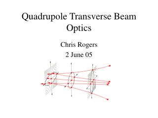
Concept for MBQ • Inclined stiff piezo actuator pairs with flexural hinges (vertical + lateral motion) • (four linked bars system) • X-y flexural guide to block roll + longitudinal d.o.f.+ increased lateral stiffness. Flexural pins
Concept for MBQ A stiff but light Fixed frame around the mobile part, objective Natural frequencies > 100 Hz
Concept for MBQ Central fixed part Magnet mounted with assembly tool
Modal analysis Type 1(simulation) soon to be tested 122 Hz 140 Hz 201 Hz 241 Hz
Comparisonsensors K.Artoos, Stabilisation WG , 21th February 2013
Displacement sensors + actuator gauges, interferometer + seismometers (calibration)
First measurements Measured still on the assembly bench, not on the floor….
First measurements • (Noisy, especiallylaterally) • Good precision • Calibration isneeded for a betteraccuracy Horizontal motion: (with gain correction for roll)
First measurements Testing of the range
Concept demonstration actuator support withstaged test benches Collocated pair EUCARD deliverable Type 1 Seismometer FB max. gain +FF (FBFFV1mod): 7 % luminosity loss (no stabilisation 68 % loss) X-y proto
2014 • Assemble type 4, all parts ready (- assembly tool) • T1 + T4 : combine stabilisation and alignment • Extensive testing stabilisation, nano positioning+ in combination. First “PACMAN tests”. • Sensor out sourcing + testing • Study alternatives for BDS actuating systems (decrease roll)
Nano positioningsensors Technological innovation: ABSOLUTE opticalencoders Fastermeasurements Heidenhain : 1nm resolution < 1000 CHF Renishaw: 1 nm resolution < 1000 CHF Smallest LSB can be used as quadrature …. 0.1 nm resolution is already possible
Integrated luminosity simulations Custom Inertial Reference mass Commercial Seismometer K.Artoos, Stabilisation WG , 21th February 2013 Courtesy J. Snuverink, J. Pfingstner et al. Stef Janssens
Resolution limitations Sensors Stabilisation Limitations: Thermal stability (*alignment) EM strayfields Sensorresolution (wavelength light) Michelson Stabilised LASER Expected maximum one order of magnitude improvement resolution in next decade (Without major technological innovation) Low freq. is where you can win the most
Nano positioning « Nano-positioning» feasibility study Modify position quadrupole in between pulses (~ 5 ms) Range ± 5 μm, increments 10 to 50 nm, precision ± 0.25 nm • Lateral and vertical • In addition/ alternative dipole correctors • Use to increase time to next realignment with cams
X-y Positioning: roll -2 legs 3 d.o.f. > parasitic roll -Measured with 3-beam interferometer -~3 μm lateral movement > ~7 μrad rotation -Early simulations suggest~100 μrad/0.5% luminosity loss (J. Pfingstner) 1&2 Parasitic roll S. Janssens, CLIC Workshop, January 2013
Mass/ActuatorResolution/ Range/k/ Bandwidth A Stress < depolarisation stress A For same Range: P Bandwidthislimited by • Actuator slew rate Remark about loadcompensatingsprings: Force Amplitude Range Frequency Load compensation reduces range + bandwidth Improves resolution *