Download

1 / 66
680 likes | 1k Views
Discuss the selection and erection methods of tower cranes based on size, location, including various common types like truck-mounted, mobile, climbing, gantry, and tower cranes, with a focus on their components and legislative requirements. Understanding the benefits and challenges to make informed decisions in managing construction projects.

E N D
Discuss the Erection of Tower Cranes. Justify the selection in terms of size, location, and erection methods
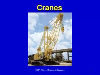
COMMON CRANE TYPES • Truck Mounted Cranes • loading / unloading purposes • may be attached with telescopic or lattice arms, slewing or fixed
COMMON CRANE TYPES Mobile Crane • normally fitted with strut (lattice) or hydraulic jibs • common for them to come with a flying jib as well • difficulties in accurate positioning of components such as cooling towers at top of building • limited site coverage
COMMON CRANE TYPES Climbing Crane • climb up a shaft within a building using a limited number of mast sections • strategic coverage yet maximizing land use in congested sites
COMMON CRANE TYPES Gantry Crane • jib supported on a 4-legged portal carried on rails with adjustable height for flexibility • normally used for material handling in the construction of caissons
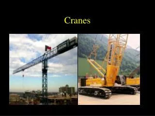
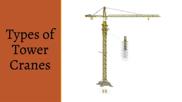
COMMON CRANE TYPES Tower Crane • extensive coverage • ability to transport materials quickly across the site • low capacity (as compared to mobile cranes) as a result of their slenderness Goliath Cranes
TYPICAL COMPONENTS OF A TOWER CRANE All tower cranes consists of the same basic parts B A S E • bolted to a large concrete pad that supports the crane • connects to the mast (or tower)
TYPICAL COMPONENTS OF A TOWER CRANE M A S T • the “body” of the crane that gives its height
TYPICAL COMPONENTS OF A TOWER CRANE S L E W I N G U N I T • gear and motor that allows the crane to rotate
TYPICAL COMPONENTS OF A TOWER CRANE J I B • the portion of the crane that carries the load • a trolley runs along the jib to move the load in and out from the crane's center
TYPICAL COMPONENTS OF A TOWER CRANE B O O M A R M contains : • crane's motors that lifts the load • control electronics • cable drum • large concrete counter weights
TYPICAL COMPONENTS OF A TOWER CRANE O P E R A T O R C A B I N
VARIATIONS TO THE TYPICAL COMPONENTS • Counter weights may be fixed at the ground level. This is normally done in situations where the load to be lifted by the tower cranes changes frequently
VARIATIONS TO THE TYPICAL COMPONENTS Derricking (Luffing) Crane • exceptionally tall buildings or in very restricted spaces • able to slew through 360o under load at only 8m slewing radius • compact slewing radius and steep jib angle (between 15° and 70°) • suitable for use on confined sites where several cranes have overlapping slewing radii
DIFFERENT SERIES OF TOWER CRANES The H seriesThe TT seriesThe K seriesThe A series H, TT and K series of bottom-slewing cranes are designed as fast-erecting cranes and are ideal for small, narrow building sites. Lifting capacities of up to 120 metric ton can be handled with hook heights of up to 34m
DIFFERENT SERIES OF TOWER CRANES The LC seriesThe EC / EL seriesThe EC-B seriesThe EC-H series The LC and EC / EL- top-slewing cranes are particularly easy to transport and assemble. The construction series ranges from 30 to 100 metric ton, with trolley jib extensions from 30.0 to 52.5m
DIFFERENT SERIES OF TOWER CRANES The top-slewing cranes in the HC series are general-purpose cranes for use in medium- to large-scale construction projects of all kinds. The series covers capacities from 800 to 5,000 metric ton with luffing or telescopic jib lengths of up to 100m; maximum loads of 80 ton and free traveling hook heights of up to 110m. The HC seriesThe HC-L seriesThe HC-T seriesThe HC-K series
LEGISLATION CP 62: 1995 Code of Practice for safe use of tower cranes Section 2 Operational Conditions • Sitting and General Safety Considerations -- adequate soil bearing capacity -- should not encroach upon public areas -- cranes must not be in the way of aircraft flight path -- adequately grounded and protected from lightning
LEGISLATION Operational Conditions • Stability -- data on the maximum forces acting at the crane’s base -- crane’s dead weight, weight of attachments and the maximum dynamic forces -- estimates on wind load -- must be plumped • Proximity Hazards -- site boundaries -- slewing limits switches could be used to restrict jib movements -- trolleying limits switches -- jib of higher crane must be at least 2m above the top of lower crane when 2 or more cranes are used -- jib of one crane should not interfere with the mast of another crane
LEGISLATION Operational Conditions • Erection and Dismantling -- sufficient working space -- inspection by competent engineer before erection and by relevant authorities -- check all bolts, locking devices, wire ropes, indicators, alarms, other safety devices, ladders, platforms, walkways, handrails, etc -- anchorage should be used when the crane exceeded free standing height -- radius indicator and load capacity chart must be fixed -- load limit switch must be fixed
LEGISLATION • Operation and Control -- should not be used for dragging and pulling of load, inclined load, piling work, demolition -- load capacity chart -- operator and signaler -- when crane is unattended, all loads must be unloaded and hook raised to highest position and minimum radius -- tag lines
LEGISLATION Section 3 Maintenance, Inspection and Repair -- logbook should be maintained for each crane -- routine inspection should be made on parts of the crane -- all cranes are required by section 31(2) of the Factories Act to be thoroughly examined by an approved person at least once in every 12 months -- any parts of the crane which is damaged and worn should be repaired or replaced with out due delay and should comply with manufacturer’s specification
Installation of Tower Cranes Submission Checklist • Site plans showing position of cranes. • Technical data for the tower cranes, including maximum in-service and out-of-service overturning and torsional moments, self-weight, horizontal reaction, and jib length. • Contractor's P.E.'s calculations and design drawings for the foundation. • A diagram of the crane indicating the location and types of safety devices to be installed. • Method statement on the system of communication between the riggers (banksmen) and the crane operator. • Clearances from relevant authority (eg. Ministry of Labour and Ministry of Defence) for the layout and height of cranes. • Documents showing that the height of the crane is within the limits imposed by the relevant aviation authority (eg. the Civil Aviation Authority of Singapore). • Latest 3 months' maintenance certificates. • Name of the riggers who shall be formally trained and shall possess the Certificates of Training from an approved authority. • Names of supervisors to supervise the use of the cranes. • Name list of authorized crane operators. • Certificates of competency for the crane operators. • Rules for the safe use of the cranes. • Capacity charts for each type of crane to be used
Guide to Carrying out Restricted Activities within the Railway Protection and Safety Zones
LEGISLATION Code of Practice, Safety and Health of Construction Worksites Part I, 1985 Chapter 9 – Lifting appliances and Equipment Section 5.3 and 5.6 • Structure -- Crane should be made from materials that absorb shock such as mild steel -- Cabin should be made of fire resisting material and provided with a fire extinguisher -- Access to the cabin should be from a safe place in the crane
LEGISLATION Section 5.3 and 5.6 • Anchorage and ballast -- Every fixed crane should either be securely anchored or be adequately weighed by suitable ballast firmly secured to ensure stability -- Counterweights should be so arranged that they do not subject the backstays, sleepers or pivots to excessive strain
LEGISLATION Section 5.3 and 5.6 • Load and radius indicator -- The maximum permitted angle of inclination of the crane jib must be clearly marked on the crane • Operation -- Jib cranes should not be moved or operated in dangerous proximity to electric power lines
Erection Procedures (refer to Video Clip and Report for comprehensive guide)
Dismantling Procedures (for telescopic, self jacking tower crane)
Inner mast Hydraulic Jacking Cage 1 1 2 2 Outer mast
Hydraulic Jacking Cage jacks inner mast downwards First section bolts released 1 1 2 2 Bolts to secure the inner mast to the second section of the outer mast
Hydraulic Jacking Cage is now in position of first section 2 2 3 3 Inner mast is jacked downwards
DISMANTLING Case Study : Proposed 30th storey HDB site along Joo Chiat Road • Singapore’s first pre-cast water tanks to be installed in HDB flats • Water tanks to be positioned on top of flats • Heavy load capacity profile • K-4 series self-jacking crane chosen
DISMANTLING Fitting of the Hydraulic Jacking Cage to the inner mast The Hydraulic Jacking Cage is fitted to the inner mast by using bolts and the sections of the Hydraulic Jacking Cage are hoisted up by the crane itself
DISMANTLING Start of the Jacking Down Process Securing the inner mast to the second section of main mast to ensure effective load transfer
DISMANTLING Right now, the entire jib arm is resting on the second main mast section, which allow the first section to be safely lifted up and dismantled
DISMANTLING After the inner mast have been secured to the second section of the main mast, the bolts securing the first main mast section to the second will be removed
DISMANTLING The Hydraulic Jacking Cage will be activated and jacked upwards to release the first section of the main mast from the second section
DISMANTLING With all the bolts removed, the first main mast section will be lifted off from its position Bottom view of the main mast Top view of the main mast
DISMANTLING Removal of the lynch pin which is holding the first section of the main mast together
DISMANTLING Lifting off the dismantled section and bringing it down to the ground by using the crane itself
DISMANTLING Securing the Hydraulic Jacking Cage to the second main mast section Lowering down of the Hydraulic Jacking Crane to the second main mast section
CRANE SELECTION Which crane to use ? Tower? Mobile? Climbing?? Selection determinants Structure Location Availability Utilization
CRANE SELECTION Structure • Tall or short • Widespan • Support for crane (tower and climbing) • Complexity of design (slewing, luffing, rotating limits)
CRANE SELECTION Location • Site layout • Site area – outside or within building footprint ?? • Vehicular access ( 10 to 15 m from site entrances ) • Coverage – ideally approaching 100% • Soil conditions • Space to assemble and disassemble
CRANE SELECTION Utilization Crane Configuration Two main determinants • Lifting weight • Lifting distance – height and reach Use load charts to determine crane configuration capabilities