Turbine Crane Plant Status & Troubleshooting Techniques
240 likes | 277 Views
Daily status and pre-job briefs for maintaining turbine building cranes, including troubleshooting methodology and common faults. Learn critical steps, safety measures, and error prevention.

Turbine Crane Plant Status & Troubleshooting Techniques
E N D
Presentation Transcript
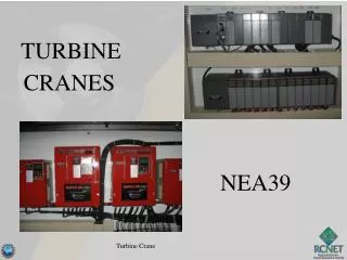
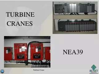
TURBINE CRANES NEA36 Turbine Crane
PLANT STATUS! General System Diagram of Palo Verde Nuclear Generating Station Legend:: Safety Injection Systems Reactor Coolant System To Switchyard Containment Building Main Steam System Main Feedwater System Main Condensate System CONTAINMENT SPRAY Circulating Water System Transformer Turbine Building Auxiliary Feedwater System Cooling Tower and Fans Safety Injection Tank Moisture Separator Reheaters MSSVs ADVs 8 8 8 Steam Generator Auxiliary Building MSIV Pressurizer MTSV Control Rods MSSS Shutdown Heat Exchanger HP LP LP LP Generator Bldg. Turbine Turbine Turbine Turbine Equipment Cooling MTCV Z From Auxiliary Feedwater Pumps Containment Spray Pump Turbine Bypass Valves Reactor Core Refueling Water Tank Condensate Pump Reactor Coolant Pump Main Condenser Low Pressure Safety Injection Pump (HP) Feedwater Heaters (LP) Feedwater Heaters Circulating Water Pump High Pressure Safety Injection Pump Feedwater Regulation Valve Main Feedwater Pump Polishing Demineralizers Containment Sump Turbine Crane PV Daily Status Report
Walk downs • Review instructions to ensure workable and adequate • Right Parts/materials/tools • Permits • Relevant Operating Experience Turbine Crane
Pre Job Briefs • Understand the Task • Critical Steps identified and OE used AND what actions are being taken in reference to these two areas • Two Minute Drills: • Hazards identified AND what are actions are you taking Turbine Crane
Procedure Use & Adherence • WO / procedure in hand & latest revision • Place keepers being used • Sign steps as you go • Follow & understand steps - STOP if can't or don't Turbine Crane
TURBINE CRANE • Terminal Objective Given references provided by the Instructor, the Plant Electrician will maintain Turbine Building Cranes as demonstrated by achieving a minimum of 80% on a written examination. Turbine Crane
. Turbine Crane
PRE-JOB BRIEF • Identify Critical Steps • Identify Error Precursors • Worst thing that can happen • Error prevention defenses to be used • Actions to assure proper configuration control Turbine Crane
TURBINE CRANE EO 1.9 Discuss the Troubleshooting Techniques performed on the Turbine Building Crane including Fault Code identification.
Troubleshooting Methodology: To effectively troubleshoot the Turbine Building Crane, you really need to observe the indications associated with the failure. The crane operator will usually be the best point of reference as to the degree and change of symptoms that are occurring or have occurred. The next level of indication will be the VFD and then PLC indications for the faults. Another level of indication is often times sensory. Turbine Crane
VFD Codes Alarm Codes: • Alarm codes may or may not result in a Base Block. • All BE (BE1 – BE7) (BE= Brake or Torque alarms • A Base Block (BB) will occur with all BE alarms with the exception of BE6 Base Block (BB) = The signal to the bases of the Insulated Gate Bipolar Transistors (IGBT) have been blocked or removed. This will prevent the transistors from “turning on” and conducting. Turbine Crane
VFD Codes Alarm Codes: • No Reset function is required • An output will occur from the drive contacts M5/M6 • Alarms BE1/BE2/BE3 are recorded in Fault History (U2-01, U2-02 and U3-01…) • BE6 is not recorded Turbine Crane
VFD Codes Fault Codes: • All Fault codes will result in a Base Block. • All codes with the exception of BE (BE1 – BE7) • A Reset function of some form IS required • An output will occur from the drive terminals MA/MB/MC • All Faults are recorded in Fault History (U2-01, U2-02 and U3-01…) and displayed on keypad. Turbine Crane
Common Faults • 2.5 X Drive rated current / 0min (instantaneous) **Typically a major fault (i.e. direct motor shorts) ***The OL1, OL2 & OC faults will have balanced output currents . Turbine Crane
Common Faults OL1– Motor Overload Fault = 150% • 1.5 X Motor FLA / 1min. (programmable) • The higher the current, the shorter the time. OL2– Drive Overload Fault = 150% • 1.5 X Drive Ref. Current / 1min **95% of OL1 & OL2 faults are caused by due to mechanical Problems (i.e. brakes, load problems etc…) • OL1– Motor Overload Fault = 150% • 1.5 X Motor FLA / 1min. (programmable) • -Thehigher the current, the shorter the time. • OL2– Drive Overload Fault = 150% • 1.5 X Drive Ref. Current / 1min • **95% of OL1 & OL2 faults are caused by mechanical problems (i.e. brakes, load problems, etc…) Turbine Crane
Common Faults GF – Ground Fault = Sums are all phases should be 0 – ort Circuit Fault (typically motor short) LF – Output Phase Loss = looks for an open phase. OL1– Motor Overload Fault = 150% • 1.5 X Motor FLA / 1min. (programmable) • The higher the current, the shorter the time. OL2– Drive Overload Fault = 150% • 1.5 X Drive Ref. Current / 1min **95% of OL1 & OL2 faults are caused by due to mechanical Problems (i.e. brakes, load problems etc…) Turbine Crane
Common Faults OV – Over-voltage = DC Bus voltage (typically 820Vdc for a 480Vac Drive) UV – Undervoltage = DC Bus voltage (typically 400V for 480Vac drive) OL1– Motor Overload Fault = 150% • 1.5 X Motor FLA / 1min. (programmable) • The higher the current, the shorter the time. OL2– Drive Overload Fault = 150% • 1.5 X Drive Ref. Current / 1min **95% of OL1 & OL2 faults are caused by due to mechanical Problems (i.e. brakes, load problems etc…) Turbine Crane