Download

1 / 9
0 likes | 6 Views
good for fracture mechahnics

E N D
Tribology Transactions ISSN: 1040-2004 (Print) 1547-397X (Online) Journal homepage: https://www.tandfonline.com/loi/utrb20 Stress Intensity Factors Evaluation for Rolling Contact Fatigue Cracks in Rails Reza Masoudi Nejad, Khalil Farhangdoost, Mahmoud Shariati & Majid Moavenian To cite this article: Reza Masoudi Nejad, Khalil Farhangdoost, Mahmoud Shariati & Majid Moavenian (2017) Stress Intensity Factors Evaluation for Rolling Contact Fatigue Cracks in Rails, Tribology Transactions, 60:4, 645-652, DOI: 10.1080/10402004.2016.1197351 To link to this article: https://doi.org/10.1080/10402004.2016.1197351 Published online: 04 Oct 2016. Submit your article to this journal Article views: 503 View related articles View Crossmark data Citing articles: 14 View citing articles Full Terms & Conditions of access and use can be found at https://www.tandfonline.com/action/journalInformation?journalCode=utrb20
TRIBOLOGY TRANSACTIONS 2017, VOL. 60, NO. 4, 645–652 http://dx.doi.org/10.1080/10402004.2016.1197351 Stress Intensity Factors Evaluation for Rolling Contact Fatigue Cracks in Rails Reza Masoudi Nejad, Khalil Farhangdoost, Mahmoud Shariati, and Majid Moavenian Faculty of Engineering, Department of Mechanical Engineering, Ferdowsi University of Mashhad, Mashhad, Iran ABSTRACT The stress intensity factors (SIFs) for multiple rolling contact fatigue cracks of a network in the Iran railway under vehicle dynamic load are evaluated in this article. Stress intensity factor evaluation under dynamic loading is simulated in three dimensions using a linear elastic boundary element code. For this purpose, a UIC60 rail with accurate geometry using a boundary element method is studied. A three-dimensional model in Franc3D is provided. Finally, the influence of the friction coefficient between the wheel and rail, crack surface friction, trapped fluid, and initial crack length on SIFs are investigated in detail. ARTICLE HISTORY Received 20 September 2015 Accepted 27 May 2016 KEYWORDS Stress intensity factors; rolling contact fatigue; crack; dynamic load Introduction Rolling contact fatigue (RCF) occurs at railway wheels and rails. It has several shapes and usually interacts with other shapes of surface damage. Recently, Ekberg, et al. (1) made an interesting effort to sort the present approaches to the RCF problem. RCF in rails is caused by the rail–wheel con- tact and leads to initiation of surface and subsurface cracks. The fatigue performance of the rails is a function of many factors, including service conditions, loading, material prop- erties, environmental factors, and manufacturing processes. In recent decades, numerous studies have been accom- plished to estimate the residual stresses. Masoudi Nejad (2) and Masoudi Nejad, et al. (3) investigated the residual stresses in the wheel and rail caused by the stress field from heat treatment of a railway wheel. The RCF damage starts with the first mechanical operation, although it is very com- plicated to detect. In fact, microscopic subsurface cracks appear and propagate, caused by the cyclic load applied to the railway wheel. Troll? e, et al. (4) presented a two-scale frictional contact fatigue crack model within the Extended Finite Element Method (X-FEM) framework to predict the fatigue life. Some works on fatigue crack growth and stress intensity factor evaluation in the wheel and rail are available in the literature (Levesque and Arakere (5); Allison, et al. (6); Deng, et al. (7)). Masoudi Nejad, et al. (8) presented a 3D finite element model for the estimation of residual stresses under variable thermal loads. The stress history is then used to calculate stress intensity factors (SIFs) and fatigue life of railway wheels. Masoudi Nejad, et al. (9) pre- sented a three-dimensional elastic–plastic finite element simulation for the estimation of residual stresses resulting from the manufacturing process and service condition in wheels in an Iranian railroad. Masoudi Nejad (10) investi- gated the stress distribution due to the press-fitting process of a bandage wheel and mechanical residual stresses due to wheel–rail operation. Finally, the effect of residual stresses on the fatigue life is assessed using damage mechanic meth- ods. Salehi, et al. (11) presented the prediction of fatigue life and crack propagation in a bandage wheel due to the stress field caused by mechanical loads and press-fitting process of a bandage wheel. They applied a 3D nonlinear stress analysis model to estimate stress field of the railway wheel in press fit- ting process. Discussion of RCF is more important. Fracture mechan- ics is widely used to predict crack growth life and several researchers improved models to predict the SIFs. To find a critical crack, it is necessary to calculate SIFs and compare with critical factors. Several researchers presented different methods to estimate the fatigue fracture plane. Bannantine and Socie (12) and McDiarmid (13) defined the fracture plane as the plane that experiences the maximum principal stress. Carpinteri, et al. (14), (15) proposed the fracture plane that coincides with the weighted mean principal stress direction. Fatemi and Socie (16) proposed to connect the fatigue fracture plane to either a mode I crack or a mode II growth mechanism. Some recent important findings in fatigue life analysis and modeling of crack growth were obtained by Guagliano and Vergani (17), Peng, et al. (18), Wallentin, et al. (19), and Sura and Mahadevan (20). Liu, et al. (21)–(23) used the finite element method to calculate SIFs in wheels, increasing the understanding of mixed mode SIFs. They calculated the RCF damage using a previously developed mixed-mode fatigue crack propagation model. In this article, a three-dimensional linear elastic boundary element code (Masoudi Nejad, et al. (24)–(26) is employed to model and accurately predict the SIFs for multiple cracks of a network using the true geometry of a rail steel. In addition, the CONTACT Khalil Farhangdoost Color versions of one or more of the figures in the article can be found online at www.tandfonline.com/utrb. Review led by Richard Neu. © 2017 Ferdowsi University of Mashhad farhang@um.ac.ir
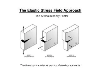
646 R. M. NEJAD ET AL. SIFs under dynamic loading (Hadipour, et al. (27)) are simu- lated in the three-dimensional model using Franc3D software (Cornell Fracture Group, Cornell University (28); Franc3D (29)). Finally, the effect of several parameters such as initial crack length, crack surface friction, and friction coefficient between the wheel and rail, initial crack angle, and trapped fluid on the SIFs in a UIC 60 rail is investigated using the sug- gested 3D model. Solid modeling for crack growth and simulation In this study, multiple cracks of a network in rails are studied. These cracks may be initiated by the near-surface plastic defor- mation caused by repeated rolling or sliding contact. The cracks propagate at a characteristic shallow angle to the surface as shown in Fig. 1. Franc3D software was used to simulate crack growth (Cornell Fracture Group, Cornell University (28); Franc3D (29)). For geo- metric modeling of a rail, the UIC60 profile, which is a prominent profile in Iranian railways, is chosen. The rail length equals the length between two sleepers and is equal to 600 mm. According to symmetryoftherails,onlyhalfofthedistanceismodeled.Thecon- tact forces acting on the rail are shown in Fig. 2. The mechanical properties of the wheel and rail are given in Table 1. The dynamic load on each wheel is 9.5 tons or 92 kN. In addition to this loading and assuming a constant rate of torque, an actuator equal to 92 N. m is applied to the wheels. Two sides of the rail are considered to be clamped. The 3D model of the rail and its cracks is shown in Fig.3whereadditionalelementsareusedtoachievethebestresults around cracks and place of the contact loading. Moreover, a semi- elliptical crack is assumed in a critical zone (Masoudi Nejad, et al. (8)).Thereasonforselectingasemi-ellipticalcrackisfieldobserva- tioninanIranianrailway.Thedimensionsoftheinvestigatedcrack arecD 1mmandaD 0.5mmwhicharetheinitialcracks. For the simulations that follow, BES, a 3D linear elastic boundary element code is used, which means that only surface meshing is required. Then SIFs are calculated for three modes, which are studied for effective parameters on the crack growth path that include the initial crack length, friction coefficient between the wheel and rail, crack surface friction, and hydraulic pressure. Figure 2. Rail contact loads. Stress intensity factors Influence of the friction coefficient between the wheel and rail Figures 4–6 show SIFs at the tip of the cracks for different val- ues of friction coefficient. According to these figures, it can be seen that increasing the coefficient of friction in the contact surface increases the SIFs. An increase in the friction coefficient of contacting surfaces increases the SIF at the crack tip, which is illustrated in Fig. 5. As the friction coefficient of the contact increases between the wheels and rail, the cracks tends to grow gradually. According to Fig. 4, it can be seen that the mode I stress intensity factor is negative for multiple cracks of a net- work. This suggests that the mode I SIF is compression for cracks. From Fig. 6, it can be seen that by increasing the friction coefficient between wheel and rail, the mode III SIF increases for multiple cracks of a network. In addition, it should be noted that the SIF for mode III is negative for crack 1, which is due to changes in shear stress. This mode is as destructive as the posi- tive one. Therefore, modes II and III are prominent in this state and mode I is compressive. This compressive nature of mode I prevents crack growth. Influence of crack surface friction The influence of crack surface friction is investigated; all other parameters are unchanged. The fluid in the crack merely lubri- cates the crack faces and reduces the crack face friction coeffi- cient. In this section it is assumed that no fluid pressure acts on the faces of the crack. Figures 7–9 demonstrate SIFs at the tip of multiple cracks of a network for various values of the friction on the crack surface. An increase in the crack friction coeffi- cient decreases the possibility of sliding between the crack sur- faces. Under this condition, mode I and mode II SIFs are increased at the crack tip and will expedite the failure. Table 1. The mechanical properties of railway wheel and UIC60 rail steels (Masoudi Nejad, et al. (8)). Component Elastic modulus (GPa) Poisson’s ratio Yield stress (MPa) Rail 206.9 0.295 483 Figure 1. Multiple cracks in a network and their names.
TRIBOLOGY TRANSACTIONS 647 Figure 3. (a) 3D modeling of rail imported in Franc 3D software and (b) crack position in the rail. Influence of trapped fluid distance between maximum pressure and coordinate origin, and b is the contact half-width. q is considered to be zero when the load is removed from the upper edge of the crack. In the second possibility, a slight change is obtained in the equations due to crack mouth closure. A detailed explanation can be found in Farhangdoost and Kavoosi (30). Figures 10–12 show SIFs at the tip of multiple cracks in a network. The surfaces are separated due to fluid trapped inside the crack and the pressure exerted on the surfaces. In this case, mode I is the dominant mode (Fig. 10). Due to fluid trapped in the crack and wedge loading that tries to open the crack tip, KI strongly increases. In addition, the crack length increases due to the higher SIF. Hydraulic pressure It is assumed that a slippery fluid cannot separate two speci- mens if there is slippery fluid in the contacting surface. This fluid is assumed to be incompressive. The fluid penetrates into the crack. The pressure appears when a counterbody covers the crack mouth and liquid in it begins to press on the crack faces during the contact cycle, causing a wedge effect. If q is assumed as hydraulic pressure in the first possibility and at the time when the crack mouth closes, and p1is the force applied to the upper edge of the crack, the following results can be achieved (Farhangdoost and Kavoosi (30)): r ffiffiffiffiffiffiffiffiffiffiffiffiffiffiffiffiffiffiffiffi ? ?2 x0 b p1Dp0 rDq6 p1.0 ? r ? 1/ 1¡ ½1? ½2? Influence of initial crack length Figures 13–15 show SIFs for multiple cracks in a network for different values of initial crack length. Based on these figures, longer cracks result in maximum SIFs. As can be seen, when the crack length increases, the difference in the values of SIFs for multiple cracks in a network (by the same length) increases. r ffiffiffiffiffiffiffiffiffiffiffiffiffiffiffiffiffiffiffiffi ? ?2 x0 b qDrp1Drp0 1¡ ½3? Here, r is the ratio of the pressure on the crack edges to the pressure at its mouth, p0is maximum pressure, x0is the
648 R. M. NEJAD ET AL. Figure 4. KIfor different friction coefficients between the wheel and rail: (a) fsD 0.1 and (b) fsD 0.3. Figure 6. KIIIfor different friction coefficients between the wheel and rail: (a) fsD 0.1 and (b) fsD 0.3. Figure 5. KIIfor different friction coefficients between the wheel and rail: (a) fsD 0.1 and (b) fsD 0.3. Figure 7. KIfor different crack friction coefficients: (a) fcD 0.1 and (b) fcD 0.3.
TRIBOLOGY TRANSACTIONS 649 Figure 10. KIfor various r: (a) r D 0 and (b) r D 1. Figure 8. KIIfor different crack friction coefficients: (a) fcD 0.1 and (b) fcD 0.3. Figure 9. KIIIfor different crack friction coefficients: (a) fcD 0.1 and (b) fcD 0.3. Figure 11. KIIfor various r: (a) r D 0 and (b) r D 1.
650 R. M. NEJAD ET AL. Figure 12. KIIIfor various r: (a) r D 0 and (b) r D 1. Figure 14. KIIfor different initial crack lengths: (a) c D 3 mm and (b) c D 1 mm. Figure 15. KIIIfor different initial crack lengths: (a) c D 3 mm and (b) c D 1 mm. Figure 13. KIfor different initial crack lengths: (a) c D 3 mm and (b) c D 1 mm.
TRIBOLOGY TRANSACTIONS 651 Conclusions Bearing Steel during Rolling Contact Fatigue,” Tribology Transac- tions, 57(3), pp 533–545. (7) Deng, S., Hua, L., Han, X., Wei, W., and Huang, S. (2015), “Analysis of Surface Crack Growth under Rolling Contact Fatigue in a Linear Contact,” Tribology Transactions, 58(3), pp 432–443. (8) Masoudi Nejad, R., Farhangdoost, Kh., and Shariati, M. (2015), “Numerical Study on Fatigue Crack Growth in Railway Wheels under the Influence of Residual Stresses,” Engineering Failure Analy- sis, 52, pp 75–89. (9) Masoudi Nejad, R., Salehi, S. M., and Farrahi, G. H. (2013), “Simula- tion of Railroad Crack Growth Life under the Influence of Combina- tion Mechanical Contact and Thermal Loads,” 3rd International Conference on Recent Advances in Railway Engineering, Tehran, Iran, April 30–May 1, 2013. (10) Masoudi Nejad, R. (2013), Rolling Contact Fatigue Analysis under Influence of Residual Stresses, M.S. Thesis, School of Mechanical Engineering, Sharif University of Technology, Tehran, Iran. (11) Salehi, S. M., Farrahi, G. H., Sohrabpoor, S., and Masoudi Nejad, R. (2014), “Life estimation in the Railway Wheels under the Influence of Residual Stress Field,” International Journal of Railway Research, 1 (1), pp 53–60. (12) Bannantine, J. A. and Socie, D. F. (1991), A Variable Amplitude Mul- tiaxial Fatigue Life Prediction Method, Mechanical Engineering Pub- lications: London. (13) McDiarmid, D. L. (1987), “Fatigue under Out-of-Phase Bending and Torsion,” Fatigue and Fracture of Engineering Materials and Struc- tures, 9(6), pp 457–475. (14) Carpinteri, A., Macha, E., Brighenti, R., and Spagnoli, A. (1999), “Expected Fracture Plane for Multiaxial Random Stress State—Part I: Theoretical Aspects of the Weight Function Method,” International Journal of Fatigue, 21, pp 83–88. (15) Carpinteri, A., Macha, E., Brighenti, R., and Spagnoli, A. (1999), “Expected Fracture Plane for Multiaxial Random Stress State—Part II: Numerical Simulation and Experimental Assessment through the Weight Function Method,” International Journal of Fatigue, 21, pp 89–96. (16) Fatemi, A. and Socie, D. F. (1988), “A Critical Plane Approach to Mul- tiaxial Fatigue Damage including Out of Phase Loading,” Fatigue and Fracture of Engineering Materials and Structures, 11, pp 149–165. (17) Guagliano, M. and Vergani, L. (2005), “Experimental and Numerical Analysis of Sub-Surface Cracks in Railway Wheels,” Engineering Fracture Mechanics, 72, pp 255–269. (18) Peng, D., Jones, R., Constable, T., Lingamanaik, S. N., and Chen, B. K. (2012), “The Tool for Assessing the Damage Tolerance of Railway Wheel under Service Conditions,” Theoretical and Applied Fracture Mechanics, 57, pp 1–13. (19) Wallentin, M., Bjarnehed, H. L., and Lund? en, R. (2005), “Cracks around Railway Wheel Flats Exposed to Rolling Contact Loads and Residual Stresses,” Wear, 258, pp 1319–1329. (20) Sura, V. and Mahadevan, S. (2011), “Modeling of Vertical Split Rim Cracking in Railroad Wheels,” Engineering Failure Analysis, 18, pp 1171–1183. (21) Liu, Y., Liu, L., and Mahadevan, S. (2007), “Analysis of Subsurface Crack Propagation under Rolling Contact Loading in Railroad Wheels Using FEM,” Engineering Fracture Mechanics, 74, pp 2659– 2674. (22) Liu, Y., Liu, L., Stratman, B., and Mahadevan, S. (2008), “Multiaxial Fatigue Reliability Analysis of Railroad Wheels,” Reliability Engineer- ing and System Safety, 93, pp 456–467. (23) Liu, Y., Stratman, B., and Mahadevan, S. (2006), “Fatigue Crack Initi- ation Life Prediction of Railroad Wheels,” International Journal of Fatigue, 28, pp 747–756. (24) Masoudi Nejad, R., Salehi, S. M., Farrahi, G. H., and Chamani, M. (2013), “Simulation of Crack Propagation of Fatigue in Iran Rail Road Wheels and Effect of Residual Stresses,” Proceedings of the 21st International Conference on Mechanical Engineering, Tehran, Iran (in Persian), May 7–9, 2013. (25) Masoudi Nejad, R., Shariati, M., and Farhangdoost, Kh. (2016), “Effect of Wear on Rolling Contact Fatigue Crack Growth in Rails,” Tribology International, 94, pp 118–125. In this study, numerical analysis was proposed for estimation of SIFs in UIC60 rails. Results were obtained based on the use of a numerical method and 3D linear elastic boundary element code. Parametric analysis of cracks in this study was performed with a boundary element method and defined effective factors such as initial crack length, loading direction, friction coeffi- cient between the wheel and rail, hydraulic pressure, and crack surface friction for multiple cracks in a network. The following conclusions can be made: 1. By increasing the friction force, slip on the crack surfaces is reduced, and therefore crack growth will decrease because the wet-lubricated rails are effective parameters in friction reduction on the crack, which can be used as an incremental factor in SIFs on mode II. 2. The fluid may penetrate into the crack and act like a wedge. Such conditions cause a sudden increase in the SIF of opening mode in multiple cracks in a network. 3. SIF analysis in the railway shows the crack growth mode as the shear combined modes II and III without trapped fluid. That is, mode I is compressive and will not have any effect on crack growth. 4. The SIF of mode I is in tension and has a significant effect on crack growth in the presence of trapped fluid. 5. The length of the initial crack has a great effect on the SIFs such that increasing initial crack length increases the SIFs at the tip of the surface crack. 6. Cracks play an important role in fatigue crack initiation in rails. Effects of size and direction of cracks is impor- tant; transverse cracks are most likely in the area where the web meets the rail head. 7. Elliptical and semi-elliptical cracks are more dangerous with respect to crack initiation by RCF than other cracks. In this article, the SIF estimation in UIC60 rails caused by mul- tiple RCF cracks in a network was investigated. Future research needs to consider interactive effects of these parameters. In addition, other rail effects, such as process parameters, bound- ary conditions, residual stress, and material properties need to be included. References (1) Ekberg, A., Kabo, E., and Andersson, H. (2002), “An Engineering Model for Prediction of Rolling Contact Fatigue of Railway Wheels,” Fatigue Fracture of Engineering Materials and Structure, 25(10), pp 899–909. (2) Masoudi Nejad, R. (2014), “Using Three-Dimensional Finite Element Analysis for Simulation of Residual Stresses in Railway Wheels,” Engineering Failure Analysis, 45, pp 449–455. (3) Masoudi Nejad, R., Shariati, M., and Farhangdoost, Kh. (2016), “3D Finite Element Simulation of Residual Stresses in UIC60 Rails during the Quenching Process,” Thermal Science, in press. (4) Troll? e, B., Baietto, M.-C, Gravouil, A., Mai, S. H., and Prabel, B. (2014), “2D Fatigue Crack Propagation in Rails Taking into Account Actual Plastic Stresses,” Engineering Fracture Mechanics, 123, pp 163–181. (5) Levesque, G. and Arakere, N. K. (2010), “Empirical Stress Intensity Factors for Surface Cracks under Rolling Contact Fatigue,” Tribology Transactions, 53(4), pp 621–629. (6) Allison, B., Subhash, G., Arakere, N., Haluck, D. A., and Chin, H. (2014), “Influence of Initial Residual Stress on Material Properties of
652 R. M. NEJAD ET AL. (26) Masoudi Nejad, R., Farhangdoost, Kh., and Shariati, M. (2016), “Three-Dimensional Simulation of Rolling Contact Fatigue Crack Growth in UIC60 Rails,” Tribology Transactions, in press. (27) Hadipour, M., Alambeigi, F., Hosseini, R., and Masoudinejad, R. (2011), “A Study on the Vibrational Effects of Adding an Auxiliary Chassis to a 6-Ton Truck,” Journal of American Science, 7(6), pp 1219–1226. (28) Cornell Fracture Group, Cornell University. “Concepts and User Guide.” Available at: http://www.cfg.cornell.edu (accessed June 26, 2014). (29) Franc3D. (1997), Concepts and User Guide, Cornell Fracture Group, Cornell University: Ithaca, NY. (30) Farhangdoost, Kh. and Kavoosi, M. (2010), “Effect of Lubricant on Surface Rolling Contact Fatigue Cracks,” Advanced Materials Research, 97–101, pp 793–796.