Download

1 / 52
520 likes | 540 Views
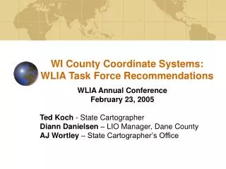
WLIA Coordinate Systems Task Force. Today’s Presentation - Jerry Mahun – WCCS: Existing vs. Proposed - Al Vonderohe – WCCS: Redesign Objectives, Strategy, and Methodology - John Ellingson – WCCS: Testing the Redesign - Ted Koch – Summary & Questions.

E N D
WLIA Coordinate Systems Task Force • Today’s Presentation - Jerry Mahun – WCCS: Existing vs. Proposed - Al Vonderohe – WCCS: Redesign Objectives, Strategy, and Methodology - John Ellingson – WCCS: Testing the Redesign - Ted Koch – Summary & Questions
WLIA Coordinate Systems Task Force • Mission: • Analyze and document the foundations of the WCCS • Investigate, analyze and document software implementations of WCCS • Investigate the redesign of the WCCS • Register WCCS with standards setting organization • Document WCCS proceedings • Develop user-focused documentation • Evaluate and make recommendations regarding statutory changes • Present TF recommendations to WLIA Board
WLIA Coordinate Systems Task Force • Task Force Members: • Tom Bushy ESRI • Diann Danielsen Dane County • John Ellingson Jackson County • Pat Ford Brown County • Gene Hafermann WI Dept of Transportation • David Hart UW-Madison Sea Grant • Ted Koch State Cartographer, Chair • Mike Koutnik ESRI • John Laedlein WI Dept of Natural Resources • Gerald Mahun Madison Area Technical College • David Moyer, Acting State Advisor Nat’l Geodetic Survey • Karl Sandsness Ayres Associates • Glen Schaefer WI Dept of Transportation • Jerry Sullivan WI Dept of Administration • Al Vonderohe UW-Madison, Dep’t of Civil & Environmental Engineering • Jay Yearwood City of Appleton • AJ Wortley State Cartographer’s Office
WLIA Coordinate Systems Task Force • Task Force Accomplishments – Past Year • 6 meetings in past 12 months • Task Force decision to move ahead with redesign • WLIB directs Strategic Initiative Grant to fund redesign • Jackson County administers redesign contract • Initial redesign work is completed and tested • Various public presentations on Task Force work • Discussions on “next steps” regarding documentation & education
Wisconsin County Coordinate System:Existing vs. Proposed Jerry Mahun, Instructor Civil & Environmental Engineering Technology Madison Area Technical College
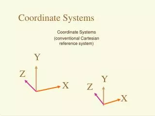
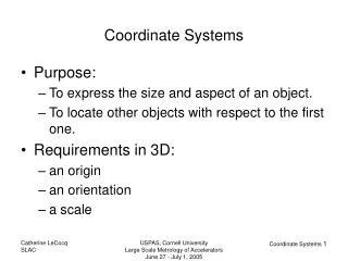
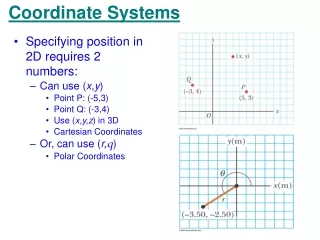
II. The WCCS – Existing vs. Proposed A. Coordinate Systems North Purpose: To express a point position by perpendicular linear distances from two axes in a 2D planar system. B Eb Nb A Ea Na East
North North North 1 unit 1 unit 90° II. The WCCS – Existing vs. Proposed A. Coordinate Systems North Desirable Characteristics: Orthogonal Parallel north lines Uniform scale in both directions East
II. The WCCS – Existing vs. Proposed A. Coordinate Systems The 3D earth doesn’t lend itself well to plane coordinates over large areas. Projecting large areas into a 2D plane distorts the earth’s surface.
II. The WCCS – Existing vs. Proposed A. Coordinate Systems 1. Earth Models If the distortion behaviors are known, they can be compensated for either mathematically or procedurally. In order to control distortion we need a mathematical model of the earth. We have three different models of the earth: - Real earth - Geoid - Ellipsoid
II. The WCCS – Existing vs. Proposed A. Coordinate Systems 1. Earth Models Real earth – physical entity on which measurements are made. Highly irregular and non-mathematical. Geoid – equipotential surface: energy on it is balanced. Primary forces: gravity pulling in and centrifugal force pushing out. The geoid is the surface to which we orient surveying equipment and make measurements.
II. The WCCS – Existing vs. Proposed A. Coordinate Systems 1. Earth Models Ellipsoid – a mathematical construct used to approximate the geoid. Start with an ellipse:
II. The WCCS – Existing vs. Proposed A. Coordinate Systems 1. Earth Models Ellipsoid – a mathematical construct used to approximate the geoid. Rotate it about its semi-minor axis:
II. The WCCS – Existing vs. Proposed A. Coordinate Systems 2. Fit an Ellipsoid Ellipsoid – a mathematical construct used to approximate the geoid. Fit it to the geoid: A single ellipsoid can’t fit perfectly everywhere due to the irregular nature of the geoid. Traditionally, an ellipsoid was fit regionally. NAD 83 uses an ellipsoid which is fit globally.
II. The WCCS – Existing vs. Proposed A. Coordinate Systems 2. Fit an Ellipsoid Ellipsoid – a mathematical construct used to approximate the geoid. Fit it to the geoid: A fit parameter relates heights. H: orthometric height N: geoid height h: ellipsoidal height
II. The WCCS – Existing vs. Proposed A. Coordinate Systems 2. Fit an Ellipsoid NAD Ellipsoid a (m) b (m) 1/f Fit 1927 Clarke 1866 6,378,206.4* 6,356,583.8* 1/294.9786982 Regional (North America) GRS 80 6,378,137.0* 6,356,752.31414 1/298.257222101* Global *defining parameters
II. The WCCS – Existing vs. Proposed A. Coordinate Systems 3. Projections Earth-geoid relationship can be modeled and Geoid-ellipsoid relationship can be modeled so Points can be transferred from the ground to the ellipsoid. A A Projections can be used to build planar coordinate systems with controlled systematic distortions. Points are projected from the ellipsoid onto developable surfaces which in turn can be rolled out flat and then form a grid.
II. The WCCS – Existing vs. ProposedA. Coordinate Systems • Two step process to obtain grid (map projection) distances from ground distances: • Or
II. The WCCS – Existing vs. ProposedA. Coordinate Systems Dground Earth’s Surface Dellipsoid Ellipsoid Factor Ellipsoid H Sea Level (Geoid) N R / (R + N + H) is called the “ellipsoid factor”. Ellipsoid factor varies with position. Note: N is negative in the drawing. R Center of Earth
II. The WCCS – Existing vs. Proposed A. Coordinate Systems 3. Projections Developable Surfaces Cylinder Cone
II. The WCCS – Existing vs. Proposed A. Coordinate Systems 3. Projections The two primary distortions are: direction (angular), and length. Direction distortions: on a planer grid, all meridians are parallel; on the real earth they converge to the poles. The larger the area covered, the greater the convergence range.
II. The WCCS – Existing vs. Proposed A. Coordinate Systems 3. Projections Length distortions - lines measured on the earth must be projected thorough different heights to get to the grid. In the process, the lines may get slightly shorter or longer: Distortion amount depends on the total height projected through and where the projection surface is with respect to the ellipsoid. If the projection is near the earth’s surface there is minimal length distortion.
93°00’ West 87°00’ West 90°00’ West II. The WCCS – Existing vs. Proposed A. Coordinate Systems 3. Projections UTM – Universal Transverse Mercator WTM – Wisconsin Transverse Mercator SPC – State Plane Coordinate
II. The WCCS – Existing vs. Proposed A. Coordinate Systems 3. Projections *Note – these are from ellipsoid to grid. There is an additional distortion due to elevation.
II. The WCCS – Existing vs. Proposed B. Why Local Systems? To minimize distortions. Direction – smaller region so convergence is smaller. Length – Bring grid closer to earth surface. Grid
II. The WCCS – Existing vs. Proposed C. Wisconsin County Coordinate Systems WCCS were designed in the mid 1990s. The smaller regions were the counties and their topography was taken into consideration. A few counties were aggregated into a single zone in some cases. There are a total of 59 coordinate systems in the WCCS.
II. The WCCS – Existing vs. Proposed C. Wisconsin County Coordinate Systems The design approach identified two heights for each county: a geoid height, and, a representative orthometric height. These were added to the axes of the GRS 80 ellipsoid to bring the ellipsoid closer to the ground (raised or enlarged ellipsoid).
System Maximum Distortion* (±) Effect on 500.000’ distance 2640.000’ distance rural 1/30,000 499.983’ (-0.017’) 500.007’ (+0.017’) 2639.912’ (-0.088’) 2640.088’ (+0.088’) urban 1/50,000 499.990’ (-0.010’) 500.010’ (+0.010’) 2639.947’ (-0.053’) 2640.053’ (+0.053’) II. The WCCS – Existing vs. Proposed C. Wisconsin County Coordinate Systems Then a projection was selected and fit; then a grid coordinate system was created. Maximum allowed length distortions were: rural : 1/30,000 urban: 1/50,000 *Note – these are from ellipsoid to grid. There is an additional distortion due to elevation.
II. The WCCS – Existing vs. Proposed C. Wisconsin County Coordinate Systems All 59 local systems exceeded the 1/30,000 and 1/50,000 by quite a bit. And since the grid was placed close to the ground over a small region, the elevation effect was minimized. Result: ground distances and grid distances are the same (except for exceptional accuracy needs)
II. The WCCS – Existing vs. Proposed D. The “Redesign” of the WCCS So if the WCCS achieved the distortion minimization goal and have been widely adopted by users, why mess with them now? Although referenced to GRS 80, each of the 59 local systems uses its own ellipsoid. By adding a geoid height and an orthometric height to the axes, the geometry of the GRS 80 ellipsoid was changed.
II. The WCCS – Existing vs. Proposed D. The “Redesign” of the WCCS Example: Most software packages when presented with different ellipsoidal parameters use an approximated transformation rather than a rigorous calculation when converting coordinates between WCCS and other conventionally defined systems.
County Ellipsoid 90° / = 90° GRS 80 Ellipsoid II. The WCCS – Existing vs. Proposed D. The “Redesign” of the WCCS Even rigorous calculations can cause small errors to be introduced when converting between a WCCS and other coordinate system since the GRS 80 and raised ellipsoid are not parallel.
II. The WCCS – Existing vs. Proposed D. The “Redesign” of the WCCS To address these issues it was decided to "redesign" the WCCS. Redesign approach: use a conventional definition of the non-conventional systems. Rather than create a new ellipsoid, it was decided to use the GRS 80 ellipsoid but fit the projection differently so only the projection was closer to the ground. Old and new approaches would both put grid close to ground but some differences would be introduced. Design goal: positional differences between the two systems could not exceed 5 mm. 5 mm was reasonably small enough: would not affect mapping and most ground survey applications.
Wisconsin County Coordinate System:Redesign Objectives, Strategy, and Methodology Al Vonderohe, Professor UW-Madison Dept. of Civil & Environmental Engineering
Wisconsin County Coordinates • Redesign Objectives: • Redesign the coordinate systems so there is no need to enlarge the ellipsoid. • There will be only one ellipsoid (GRS80) for everyone. • Redesigned (Version 2) coordinates should not differ by more than 5mm from the originals anywhere on any projection. • Legacy data will be preserved. • Existing and new data can be combined without transforming either.
Wisconsin County Coordinates • Redesign Strategy: • Multiply scale factor on Central Meridian (Transverse Mercator) or Central Parallel (Lambert) by (R + N + H) / R to obtain provisional scale factor. • Causes ellipsoid factor and scale factor to be approximate reciprocals of one another, so when they are multiplied together the result is approximately equal to one. • Adjust the false northing, false easting, and provisional scale factor to account for effects of the difference in eccentricities of the two ellipsoids (GRS80 and enlarged).
Wisconsin County Coordinates • Methodology: • Use DNR statewide map to obtain boundaries for each projection. • Generate a 0.5-mile grid of test points within a 2-mile buffer for each projection.
Wisconsin County Coordinates • Methodology: • Compute provisional scale factor for each projection. • Using provisional scale factor, compute provisional county coordinates for each grid point. • Compute original county coordinates for each grid point. • Develop observation equations for each grid point:
Wisconsin County Coordinates • Methodology: • Compute least squares solution of about 10,000 equations for each projection to obtain shifts in false northing and false easting, and multiplier for provisional scale factor. • Final Transverse Mercator parameters are: Number of Transverse Mercator parameters is reduced from 7 to 5.
Wisconsin County Coordinates • Methodology: • Final Lambert parameters are: • Number of Lambert parameters is reduced from 8 to 5. • o(original) is computed from 1(original) and 2(original). • Coordinate origin is shifted to o, o. • No(original) at new coordinate origin is computed, not given.
Wisconsin County Coordinates • Methodology: • Compute differences between Version 2 and original coordinates at each grid point. • Find maximum shifts in northings and eastings to check against 5mm tolerance. • Prepare isoline (contour) maps of coordinate shifts.
Wisconsin County Coordinates • Results: 72 Counties 59 Coordinate Systems 24 Lambert 35 Transverse Mercator
Wisconsin County Coordinates • Results: • All coordinate systems meet the redesign criterion: • All coordinate shifts are less than 5mm. • Typical coordinate shifts range from –3mm to +3mm. • Some counties have maximum shifts of less than 1mm. • Maximum shifts are in Oneida and Vilas (Lambert) and Ashland and Forest (TM).
Coordinate Shifts Buffalo County (Typical Transverse Mercator) Shift in Northing (mm) Shift in Easting (mm)
Coordinate Shifts Ashland County (Worst-Case Transverse Mercator) Shift in Northing (mm) Shift in Easting (mm)
Coordinate Shifts Forest County (Worst-Case Transverse Mercator) Shift in Northing (mm) Shift in Easting (mm)
Coordinate Shifts Burnett County (Typical Lambert) Shift in Northing (mm) Shift in Easting (mm)
Coordinate Shifts Oneida County (Worst-Case Lambert) Shift in Northing (mm) Shift in Easting (mm)
Coordinate Shifts Vilas County (Worst-Case Lambert) Shift in Northing (mm) Shift in Easting (mm)
Wisconsin County Coordinates • Validation: • Independent testing by four individuals using various software packages and programming techniques. • All have concluded that the redesign meets the 5mm criterion.
Wisconsin County Coordinate SystemTesting the Redesign John Ellingson, Land Information Coordinator Jackson County