Download
1 / 36
460 likes | 615 Views
Learn FPGA design theory and practice, including gateware workflows, PRBS, FPGA serialization, and digital signal processing. Understand hardware description languages and design implementation flow for FPGA logic cells.

E N D
Advanced FPGA design Andrea Borga andrea.borga@nikhef.nl
Outline • First part: theory • … from the previous lesson • Considerations on Hardware Description • Gateware workflow • Takeaway thoughts • Second part: practice • Eye diagrams • Pseudo Random Bit Sequences (PRBS) • FPGA serializers and deserializers
FPGAs : Field Programmable Gate Arrays • Array (Matrix)like structure made of: • Look-Up-Table (LUT) to implement combinatorial logic • Flip-Flops (FF) to implement sequential logic • Routing network to interconnect the logic resources • I/O logic to communicate with outside logic • Clock Management: Phase Locked Loops (PLLs), Digital Clock Managers (DCMs) • Hard-Macros: Digital Signal Processing (DSP) cells, SRAMs,PCIe, Gigabit Transceivers,etc. Configurable Logic Block (CLB)
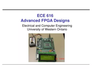
Example: Xilinx Virtex-7 development board http://www.xilinx.com/products/boards-and-kits/dk-v7-vc709-g.html
Digital (Gateware) Design is NOT programming • Parallel • Processing • Sequential • Processing • Single Core CPU • Hyper-Threaded • Graphics Processing • Unit (GPU) • Single Core CPU • Multi Core CPU • FPGAs • Programming • Code is written and translated into instructions • Instructions are executed sequentially by the CPU(s) • Parallelism is achieved by running instructions on multiple threads/cores • Processing structures and instructions sets are fixed by the architecture of the system • vs. • Digital (Gateware) Design • No fixed architecture, the system is builtaccording to the task • Building is done by describing/definingsystem elements and their relations • Intrinsically parallel, sequential behaviour is achieved by Finite-State-Machines (FSMs) and registers • Description done by schematics or a hardware description language (HDL)
Hardware Description Language (HDL) • As the name suggests it is a language used to describe hardware: so you have to use it to do so! • Let’s discuss the simple example of a wait statement • In C (Unix, #include <unistd.h>) sleep(5);// sleep 5 seconds • In VHDL this is not synthesizable, but you can use it in test benches • This is (one) way to do it in synthesizable VHDL not a realistic clock (1sec) this is enormous!
Gateware design workflow… a la carte! • Schematic • or HDL Design • Behavioral Simulation • IP Cores/Macros • Synthesis • Functional Simulation • Post translate/map • simulation models • Translate/Map • SDF* • Constraints • Timing Simulation • Place & Route • Program Device • (bitfile) • Debugging • * Standard Delay Format
Gateware design workflow… a la carte! 2 1 3 Implementation flow: what turns a line of code into a blinking LED? Verification flow: why is the statement above not (always) true! Design constraining: how to force your game rules
Implementation flow: synthesis • Register Transfer Level (RTL) • a design abstraction which models a synchronous digital circuit in terms of the flow of digital signals (data) between registers and logical operations performed on those signals. (http://en.wikipedia.org/wiki/Register-transfer_level) Elaborated (RTL) Design counter control registered output counter Flip-Flops Xilinx Vivado 2014.4 design flow
Implementation flow: synthesis • Synthesis • translates the schematic or HDL code into elementary logic functions • defines the connection of these elementary functions • uses Boolean Algebra and Karnaugh maps to optimize logic functions • generates a device independent net list 1815 - 1864 1924 - Synthesized Design Xilinx Vivado 2014.4 design flow
Implementation flow: synthesis • Synthesis • translates the schematic or HDL code into elementary logic functions • defines the connection of these elementary functions • uses Boolean Algebra and Karnaugh maps to optimize logic functions • generates a device independent net list 1815 - 1864 1924 - Synthesized Design Xilinx Vivado 2014.4 design flow
Implementation flow: mapping and routing • Translate/Mapping • translates the device independent net list into technology specific elements • checks the content of black boxes (e.g. IP cores) • checks if the design can fit the target device • maps these elements into the FPGA logic cells • Place andRoute (P&R) • places the basic elements on the logic cell grid • routes the signals between the logic cells • can be “guided” by constraints: • location constraints • timing constraints Virtex-7 690T floorplan Xilinx Vivado 2014.4 design flow
Implementation flow: routing the counter Virtex-7 690T floorplan Xilinx Vivado 2014.4 design flow
Implementation flow: routing the counter • Perfect example of a badly constrained design! Virtex-7 690T floorplan Xilinx Vivado 2014.4 design flow
Verification flow: simulation • Verification of a design by an HDL simulator. • Industry standard → MentorGraphicsModelsim (or Questasim) • Try out some free alternatives → Icarus Verilog (http://iverilog.icarus.com/) • Try out some free alternatives → GHDL (http://ghdl.free.fr/) • Event-based simulation to recreate the parallel nature of digital designs • The simulator time is sliced in delta delays • At each step of the delta delay all clauses (e.g. clock rising edge) are evaluated • The outcome of an event is computed and the logic updated • Different levels of simulation: • behavioral: fastest, simulates only the behavior of the design Example: MentorGraphicsQuestasim
Verification flow: simulation • functional: fast, uses realistic functional models for the target technology the least used by HDL designers … why? • Mostly because these days you can (almost) trust your tools (a bit) more • What happens if you use the VHDL statement? signal <= ‘X’; -- unknown (misused to connect to anything) • post translate and map simulation models: similar to the above but with information (about the actual primitives) of the translation and mapper steps • timing: slow, most accurate. Uses Place&Route design + SDF (StandardDelayFormat) • in the past was used to detect routers errors in placing designs… when routers where not so smart and FPGAs where not so fast! • what if the propagation delays of the bits of our counter where not equal? • or greater than the clock speed?
Verification flow: debugging • Your desingis up… and alsorunning? • Most FPGA vendors provide internal logic analyzer cores • ISE ChipScope, Vivado Set up Debug(Xilinx) • SignalTap(Altera) • Can be embedded into the design and controlled by JTAG • Allow also the injection of signals • It is at times extremely useful to spy inside the FPGA… but this doesn’t replace an oscilloscope… as signal integrity issues can be on the PCB • Remember… it’s hardware! • Example: ChipScope waveform window (Xilinx ISE)
Design constraining • Remember: you are describing your hardware! • Constraining is becoming so important that it is turning into a (not yet) standardized language of it own: • .qsf: Quartus II Setting File (Altera) • .sdc: Synopsis Design Constraints (de facto standard) • .ucf: User Constraint File → .xdc Xilinx Constraint File (Xilinx) • Two types of constraints: • Location constraints • Geographical position and pin related • Timing constraints • clock and timing related
Design constraining: location • FPGAs usually provide a large number of I/O pins for communication with the outside world • Large variety of I/O standards supported: 3.3V CMOS, 2.5V LVDS, SSTL, … • I/O pins can be assigned more or less freely • BUT • I/O cells are grouped in I/O banks→ All cells in an I/O bank need to use either the same standard or a similar one (with the same voltage level), e.g. 3.3V CMOS is not compatible with LVDS • LVDS signals always come in dedicated pairs • Clocksignals should use dedicated clock input pins → routed internally over a dedicated network • High-Speed serial interfaces (PCIe, Gigabit-Transceivers) or hard macros might need dedicated pins as well • Good Practice • Try to locate pins belonging to one design module close to each other → avoid routing across chip • PCB Designers: • Check your I/O assignment with a preliminary design with only I/O pins instantiated • Check for SSN (Simultaneous Switching Noise) • Use back-annotation of I/O pins to optimise fan-out and routing of signals
Design constraining: location • Example: Virtex-4 LX40-FF1148 Package & Pinout View
Design constraining: timing • Timing constraints • clock period • setup and hold times • path delays: highlight critical connections • false paths: force ignoring some connections • See for example: Xilinx Vivado Using Constraints (UG903) • Remember the story of the propagation delay in the timing simulation?(the positioning of Flip-Flops?) • If you do a good job constraining… you can spare yourself the timing simulation! Xilinx Vivado 2014.4 design flow
Takeaway: don’t ignore reports! • Learn to carefully review reports • The reason why your design is not functioning as intended… can be right in front of your eyes! • Especially check timing and… don’t run designs that haven’t met timing! Xilinx Vivado 2014.4 design flow
Takeaway: scripting for Gateware designs • Design tools can be scripted: Tool Command Language (TCL) • Parameters/Options can be passed via command-line (makefile, shell scripts) • You have much more control and reproducibility on your procedures (you can forget about checking a tick-box, and you will, sooner or later…) • allows for complete automation → design servers and nightly build Xilinx Vivado 2014.4 • Simulators can be controlled with TCL and even used to create test benches (slower but extremely flexible) MentorGraphicsQuestasim v10.2
Takeaway: more tips • Describe your hardware: think hard…ware! • RT…M! Seriously… you HAVE to, especially with FPGAs (family overview, DC and Switching, clock resource, Transceiver Guides, Package and pinout) • Consider your FPGA full at 70% or you’ll get nice surprises from your router… • Digital designs are analog in essence (especially with ever higher clock frequencies) • Share shareshare… • Celebrate your achievements!
FPGAs… so what? Practical example
ISO / OSI model: You are here… • International Organization for Standardization / Open System Interconnection: if you are talking about engineering, can’t do a talk without! • It is a conceptual model that characterizes and standardizes the internal functions of a communication system by partitioning it into abstraction layers • A layer serves the layer above it and is served by the layer below it by function by protocol FPGAs http://en.wikipedia.org/wiki/OSI_model
System Architecture: You are here… • A Gigabit-Transceiver is one of the many gadgets surrounding gate logic widely available in modern FPGAs • Very popular since a lot of applications have demanding and fast (serial) I/O requirements ? Gigabit-Transceiver X
Eye Diagrams • An eye diagram (eye pattern) is the first measure of the quality of a transmission channel: how good are my “ones” and “zeroes”? • Essential information on transmission quality can be obtained from these diagrams : amplitude (voltage) stability, time stability,, etc. • It is all about the probability to sample the signal correctly Instrument: Agilent 86100C DCA-J
Pseudo Random Bit Sequence (PRBS) • A PRBS is a sequence of bits that are pseudo-random. That is, they are not really random but they can be used where a good approximation to random values is required→ test vectors, white noise • They are often implemented using Linear Feedback Shift Registers (LFSR) • The arrangement of taps for feedback in an LFSR is a polynomial mod 2 • PRBS = x7+ x6+1 • Maximum number of sequences: 2n-1 • It starts from a “seed value”, the only forbidden state is all-zeroes (no exit) Fibonacci LFSR http://en.wikipedia.org/wiki/Linear_feedback_shift_register
Xilinx Virtex-7 Serializers Deserializers FPGA pins to PCB board User Logic • Good news: the PRBS is a built-in function of most modern transceivers! • The next step is to write your own code and drive a link! www.xilinx.com/support/.../user.../ug476_7Series_Transceivers.pdf
Pitbullen! • We may face (very) difficult problems… • Never let go! • It may take a while… but victory will be yours! • Thank you very very much to: Torsten Alt (FIAS) and Peter Jansweijer (Nikhef)