Download
1 / 25
260 likes | 431 Views
TFE: The New Heartbeat of Loran T. P. Celano, Timing Solutions Corporation LT Kevin Carroll, Loran Support Unit. Introduction. The USCG is leading an effort to modernize the LORAN-C network of transmitting stations in the U.S.

E N D
TFE: The New Heartbeat of Loran T. P. Celano, Timing Solutions Corporation LT Kevin Carroll, Loran Support Unit
Introduction • The USCG is leading an effort to modernize the LORAN-C network of transmitting stations in the U.S. • Part of the modernization effort is to replace the time and frequency generation system at transmitting LORAN-C stations • Existing hardware is outdated and requires replacement • The new design integrates all of the current LORAN-C timer functionality with new timing technology into a single system • New timing component designed to maximize the benefits of co-located cesium standards • System is designed to satisfy the current operational requirements as well as accommodate future requirements with minimum modifications • System functions aid in meeting the FAA’s RNP 0.3, Coast Guard’s Harbor Entrance and delivering Stratum I timing performance to LORAN timing users
Existing System • The existing time and frequency equipment is a conglomerate of equipment designed and installed over the last 40+ years • Each station has a different list of equipment depending of master/secondary and dual/single rated • The system is based primarily on hardware technology that is outdated • Communication capability differs depending of component • Different hardware architecture forces communication capability to lowest level • System does not capitalize on the three cesium clocks for timing accuracy • Cesiums are independently operated • No automatic control of cesiums to USNO-UTC
Existing System Components • The current timing and frequency suite is collection of up to 30 separate components. • 1970’s Vintage • Timer Units • Timer Set Control • Alternating Blanking Unit • Remote Control Interface • Communication Adapter • Waveform Panel • SSX IF • LSM IF • 1960’s Vintage • Emergency Stop • Distributions Amplifiers • Frequency Patch Panel • Signal Alarm Unit • Time Counter • Electronic Pulse Analysis • Cycle Compensation Circuit • 1980’s Vintage • Phase Micro-stepper • Time Counter • Multi-programmer 1990’s Vintage • Time of Transmission Patch Panel * • Timer Counter * • GPS Timing Receiver * • Time Reference Generator * • Automatic Blink System * Master Stations only
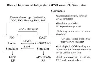
TFE System Level • TFE consists of two redundant signal paths that generate transmitter drive signals with a known relationship to UTC(USNO) • Each redundant half of the system operates independently to control primary frequency standards, generate transmitter drive signals and measure time differences • Single (non-redundant) unit for distributing frequency signals from clocks for diagnostic use
TFE Functional Diagram • Clock Ensemble/UTC Recovery • GPS measurements • Inter-clock measurements • Timescale algorithm • Clock steers • Loran Signal Generation • PCI/TOC Generation • LPA implementation • Transmitter Drive Signals • Diagnostic Outputs • TD Measurements • UTC Recovery TD • Loran Recovery TD • TOT TD’s • Additional Measurements • Closed Loop Control • Signal Phase Control • ABS • Signal Phase Control
Timescale Computation and Clock Steering • System utilizes three cesiums to compute a local timescale that is steered to UTC(USNO) via GPS • 15 ns (RMS) UTC time recovery performance • Kalman filter models clocks and predicts clock performance when measurement data isn’t available • System can flywheel through GPS system outages • Three clock timescale provides real-time clock fault monitoring as well as superior stability • System designed to maximize the benefit of three atomic standards at each LORSTA • Timescale reduces to two or one clock if three clocks are not available
TFE Functional Diagram • Clock Ensemble/UTC Recovery • GPS measurements • Inter-clock measurements • Timescale algorithm • Clock steers • Loran Signal Generation • PCI/TOC Generation • LPA implementation • Transmitter Drive Signals • Diagnostic Outputs • TD Measurements • UTC Recovery TD • Loran Recovery TD • TOT TD’s • Additional Measurements • Closed Loop Control • Signal Phase Control • ABS • Signal Phase Control
LORAN Signal Generation • LORAN signal generation is accomplished in programmable firmware in the Loran Integrated Timer and Signals (LITS) chassis • Unit receives 5 MHz from PFS and generates PCI, TOC, LI, and transmitter drive signals for two independent rates • All LORAN signals originate from a single 5 MHz input (all signals are coherent) • Command and control accomplished via RS-232 • ABS control accomplished using direct digital lines • All system outputs on rear of chassis • Transmitter drive signals output on multi-pin connector • Copies of all signals for monitoring/diagnostic purposes • Spare connectors for future use
LORAN Signal Generation (cont’d) • Local phase adjustments (LPAs) inserted via a direct digital synthesizer (DDS) that creates a phase change by changing the frequency of the 5 MHz signal over a fixed time interval • 5 MHz in, 5 MHz out tunable synthesizer • Control method results in phase changes without discontinuities in transmitted data • Smooth transition reduces transmitter jitter during LPA • LPAs can be completed over settable time period (time interval for frequency change is a settable parameter)
TFE Functional Diagram • Clock Ensemble/UTC Recovery • GPS measurements • Inter-clock measurements • Timescale algorithm • Clock steers • Loran Signal Generation • PCI/TOC Generation • LPA implementation • Transmitter Drive Signals • Diagnostic Outputs • TD Measurements • UTC Recovery TD • Loran Recovery TD • TOT TD’s • Additional Measurements • Closed Loop Control • Signal Phase Control • ABS • Signal Phase Control
Signal Measurements • Six channel, sub-nanosecond event timer used to time tag the rising edge of the signals of interest • PCI, TOC, 1 PPS, RF Gate, RF Pulse (detected pulse from transmitter) • One timer per rate • Timer allows computation of the time differences by subtracting time tags from any pair of inputs • Six simultaneous channels is more efficient than standard two-channel time interval counter • For example TOC is compared to 1 PPS to verify timing and also processed with RF Pulse and RF Gate as time of transmission TDs • Unit allows for future time differences of interest to be added to system output
TFE Functional Diagram • Clock Ensemble/UTC Recovery • GPS measurements • Inter-clock measurements • Timescale algorithm • Clock steers • Loran Signal Generation • PCI/TOC Generation • LPA implementation • Transmitter Drive Signals • Diagnostic Outputs • TD Measurements • UTC Recovery TD • Loran Recovery TD • TOT TD’s • Additional Measurements • Closed Loop Control • Signal Phase Control • ABS • Signal Phase Control
Closed Loop Transmitter Control • Automatic Phase Adjustments (APAs) are inserted based on a proportional control loop closed around the transmitter • RF feedback from transmitter drives a detection circuit TTL pulse produced based on SZC pulse measured in timer against TOC or RF Gate • Loop parameters control system’s response to transmitter delay changes • Time constant: how quickly the system responds to delay changes • Minimum Steer: APA not inserted unless error is large enough • Steer Interval: how often transmitted phase can be adjusted • APAs inserted using identical method as LPAs (DDS freq change) • APAs can be computed based on UTC or LORAN data • System can function without GPS using casualty receiver
Closed Loop Transmitter Control Data System deliberately set off target time to show performance of proportional loop
Closed Loop Transmitter Control Data APAs required occasionally to compensate for timing events
TFE Functional Diagram • Clock Ensemble/UTC Recovery • GPS measurements • Inter-clock measurements • Timescale algorithm • Clock steers • Loran Signal Generation • PCI/TOC Generation • LPA implementation • Transmitter Drive Signals • Diagnostic Outputs • TD Measurements • UTC Recovery TD • Loran Recovery TD • TOT TD’s • Additional Measurements • Closed Loop Control • Signal Phase Control • ABS • Signal Phase Control
Integrated Automatic Blink System (ABS) • ABS is critical for LORAN’s HMI performance for integrity protection • Monitors the transmitted signal for out-of-tolerance conditions through RF feedback • Three selectable patterns for notifying the user • System utilizes direct digital lines to allow fast transition to blink • Blink control not affected by comms or OS latency • System transitions to blink in less than one second after problem detection • Blink is initiated in hardware based on programmable rule set • Phase of transmitted signal vs local TOC estimate • Phase error in transmitted pulses • Lack of RF return from transmitter • Time step in cesium standard • All of the ABS parameters can be adjusted to suit the performance of the transmitter • As future transmitter jitter improves, the tolerances can be set tighter and/or averaging time in the ABS algorithm can be reduced
Technical Comparison of Systems • There are significant performance advantages to the new system
Support Comparison • Improved support aspects of the new system provide some of the greatest benefits
Future Requirements • TFE has been designed with the forethought that LORAN-C will be evolving over next 10 years • Modular design that isolates timing to the one chassis and LORAN signals in LITS chassis • Timing chassis consists of independent modular slots that isolate functionality to specific components • LITS chassis has been designed using field programmable hardware to facilitate easy modifications • FPGA implementation for signal generation • Microprocessor for external interface and control • LITS design also includes empty expansion slot and spare connectors to facilitate addition of future capability to LORAN signal structure • System utilizes an IP socket interface that enables remote control • All command, control and status achieved using standard IP interface with ASCII command set
Conclusions • The new LORAN-C transmitter timing system provides a single integrated system to bridge the gap between the cesium standards and the transmitter • Old functions are replaced with higher performance equipment that is more reliable and flexible • Logistics are simplified with respect to Configuration Management, maintenance, and repair • New timing architecture provides system flexibility to address future requirements and performance enhancements • System can support a large range of possible architectures including new rates, data transfer capability and higher HMI responsibility