Download
1 / 31
310 likes | 336 Views
Explore the FAZIA detector project, its components, results, and challenges faced in nuclear particle physics research. Learn about detection techniques and improvements in identification thresholds and radiation damage mitigation. Keep updated on R&D prototypes and performance analysis.

E N D
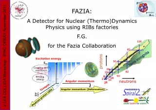
126 Excitation energy Eexc 82 Coupling with continuum Binding energy protons 50 Angular momentum J Isospin 28 Angular momentum (Deformation) 82 20 N- Z N+Z 50 8 Neutron-proton ratio 28 2 20 neutrons 8 2 FAZIA: A Detector for Nuclear (Thermo)Dynamics Physics using RIBs factories F.G. for the Fazia Collaboration V LEA COLLIGA Workshop - IPNO ORSAY November 2011 Terra incognita
The FAZIA DETECTOR project: • Multi-detector basic Telescope = DE(Si)-DE(Si)-E(CsI) • with low (A,Z) identification threshold. • Contents: • What did we learn? • Results (Phase I R&D) • “problematic” points • Demonstrator Phase • Memorandum of Understanding (SPIRAL2PP deliverable) V LEA COLLIGA Workshop - IPNO ORSAY November 2011
TASK 5.3 SPIRAL2PP FAZIA PhaseI - R&D Prototypes (phase1) Dec. 2007 – light ions, low energy V LEA COLLIGA Workshop - IPNO ORSAY November 2011 July & November 2009 – heavy ions, high energy PSA front and rear side PSA vs Radiation damage May 2010 + nTDstrip-detectors November 2011 PSA + TOF – diff electronics
1 – DOPING UNIFORMITY 2 – AVOID (as far as possible) CHANNELING FAZIA: what did we learn? RECIPE FOR HIGH QUALITY CHIPS Ingot selection from the producer, controlled doping (at about r=3000 ohm.cm) and use of nTD technology for best uniformity (FWHM less than 1%) V LEA COLLIGA Workshop - IPNO ORSAY November 2011 Ingot orientation and choice of the cut along special 'random' directions (7deg to <100>); slices of 300 and 500 microns
Si1 Si1 Si2 Si2 ER DE DE ER Results 1) Improvement of the “usual” DE/E technique V LEA COLLIGA Workshop - IPNO ORSAY November 2011 2) Quantitative results concerning PSD (Identification using ONE silicon detector) 100MS/s 14bit digitizer Q and I signals
Si1 Si2 DE ER Results for usual DE/E technique V LEA COLLIGA Workshop - IPNO ORSAY November 2011
Si1 Si2 DE ER Results for usual DE/E technique V LEA COLLIGA Workshop - IPNO ORSAY November 2011
Si1 Si2 DE DE Results for usual DE/E technique CsI(Tl) ER V LEA COLLIGA Workshop - IPNO ORSAY November 2011
Si1 Si2 DE DE Results for usual DE/E technique CsI(Tl) ER V LEA COLLIGA Workshop - IPNO ORSAY November 2011
Si1 Si2 DE ER Z=54 Results for Pulse Shape Analysis PSA: only one Silicon is used Si1 Si2 129Xe+Ni 35 A.MeV ER V LEA COLLIGA Workshop - IPNO ORSAY November 2011 100MS/s 14bit digitizer Digital PSA results: one digitizer, 6 GeV full scale (a.u) Punch-through particles. Particles identified by Silicon detector Si2 Effective threshold: about 40 µm Silicon ER-Q signal Rise Time FAZIA data (LNS)
Si1 Si2 129Xe+Ni 35 A.MeV ER DE ER Punch-through particles Mg Ne O C Hic sunt leones Be ER/Imax Results for Pulse Shape Analysis PSA: only one Silicon is used V LEA COLLIGA Workshop - IPNO ORSAY November 2011 100MS/s 14bit digitizer Digital PSA results: one digitizer, 0.7 GeV full scale • QUESTION of GAIN: • 6GeV full scale Z Id. • 0.7 GeV full scale Z and A Id. FAZIA data (GANIL2010)
Fazia performances...slow ions The big challenge of identification for ions stopped in one Silicon stage PSA in Si V LEA COLLIGA Workshop - IPNO ORSAY November 2011 L.Bardelli et al.: published on NIM2011 avail. on line 21.6.11 Current max Current signal Xe beam 35AMeV t Use of Figure of Merit to put quantitative limits on thresholds Current max Z identification S.Carboni et al, accepted on NIM 2011
Results for Pulse Shape Analysis Factor of Merit of discrimination between 2 Z’s V LEA COLLIGA Workshop - IPNO ORSAY November 2011 Good FoM=0.7 Quantitative results using (E, Qrise time) and (E, Imax) S.Carboni, accepted on NIM S.Carboni, Firenze
Results for Pulse Shape Analysis Z Identification Thresholds (FoM=0.7) ENERGY (MeV) ENERGY (A.MeV) V LEA COLLIGA Workshop - IPNO ORSAY November 2011 Comparison of Z identification thresholds between DE-E and PSA S.Carboni, Firenze
Sources of problems for PSD • Radiation damage • Id. Threshold of a few A.MeV • Detector mass-production: the mass-production of the detectors is fully feasible and at a reasonably low cost. • The problem is that we depend on only one • manufacturer for each item: TOPSIL for wafers • and FBK for detector construction. V LEA COLLIGA Workshop - IPNO ORSAY November 2011
Problems: radiation damage Charge rise time information ENERGY V LEA COLLIGA Workshop - IPNO ORSAY November 2011 V LEA COLLIGA Workshop - IPNO ORSAY November 2011 Implantation or Punching through Xenon ions slow-control system was programmed in such a way as to continuously measure treverse current and to correct the applied voltage for the ohmic drop on the bias resistor, in order to keep the voltage constant across the detector The radiation damage is present mainly on zones where ions are implanted, while very minor effects are observed on the detector regions traversed by ions. S.Barlini, N.Le Neindre (Firenze, LPCCaen)
Problems: radiation damage V LEA COLLIGA Workshop - IPNO ORSAY November 2011 Detector exposed to a high flux of elastically scattered Xenon ions The final conclusion: in order to keep the optimal performance level of PSA in Silicon for the highest examined Z values, the fluence of heavy implanted ionin the detector has to be kept to a value lower than about few 107/cm2. Analysis - S.Barlini
Si1 Si2 3rd vs 2nd moment of current signals DE ER Exp+Simulation Y axis: measured energy X axis: measured rise-time + simulated ToF over 1.1m and 0.5 ns FWHM (smoothly merged) Problems: PS Identification threshold Presently under TESTS @ LNS about 40 µm Silicon under which no identification is possible How can we lower the Thresholds at least for mass identification? The Time of Flight is necessary Technological Development: better choice for the silicon Limiting the sheet resistanceRΩ (do not degrade the shape) Assure photo-sensitiveness (laser, SCT) V LEA COLLIGA Workshop - IPNO ORSAY November 2011 no Al deposition (bare Si) t=6.7ns FBK silicon detectors: the right receipt for the metallic layer has been found ≈25nm Al S.Carboni
LNS Ongoing TEST Some preliminary test: PSA mass resolution Playing with the applied voltage Playing with the gain/dynamical range V LEA COLLIGA Workshop - IPNO ORSAY November 2011 PRELIMINARY
FAZIA demonstrator (2011-2015) • FAZIA PHASE2 “demonstrator & physics” : • Built a demonstrator of 192 telescopes Si/Si/CsI with “all” the finals (4p detector) electronics, mechanical solutions. • With this demonstrator coupled to existing multi-detectors (INDRA, GARFIELD, CHIMERA,…), realize experiments (GANIL, SPIRAL2, LNL/SPES, LNS). V LEA COLLIGA Workshop - IPNO ORSAY November 2011 12 BLOCKS 48 MODULES 192 TELESCOPES Si/Si/CsI
FAZIA Phase2-demonstrator Block (12 telescopes) • MILESTONE 2012 • 1 Block of telescopes within half 2012 • Mechanics for the telescopes • Backplane for 8 FEE (each 6 channels) • Cooling system • Block card with opt. fiber • Regional level and DAQ architecture and Trigger. V LEA COLLIGA Workshop - IPNO ORSAY November 2011 Block: backward view.
FAZIA Phase2-demonstrator CsI(Tl) new wrapping material Gain of 20% in light output • Twomaterialshavebeentestedasinternalwrappingmaterial for a best light collection: • whiteMillipore ISEQ 0.2 mm • 3M Vikuiti ESR reflectingmaterial (IPNOrsay, INFN-Firenze) Almost all CsI(Tl) crystals for the Demonstrator have been ordered by France, Italy and Romania. About 70% have been tested at ORSAY. Very high quality of the long crystals (10cm) Request fulfilled by the company. Optimal results with the new wrapping. Coupling with FBK new photodiodes under test at LNS (present experiment) V LEA COLLIGA Workshop - IPNO ORSAY November 2011 “usual” wrapping new wrapping
FAZIA Phase2-demonstrator FRONT-END & DAQ FEE CARD (IPNOrsay, INFN-Firenze) V LEA COLLIGA Workshop - IPNO ORSAY November 2011 • FEE CARD (IPN Orsay) • with collaboration from Na-Fi/LNL • 6 channels/card • 6 LowNoisepreamplifiers: twooutputs (charge and current) • DynamicalRange up to 3.5GeV/6Volt • SignalFiltering, Shaping and Sampling 250MHz/14bit BLOCK CARD INFN Na The BC handles the passage of the output signals from the FEE to the optical fibers. Moreover the BC accepts the validation command from the specialized external trigger and the 'slow controls' commands spreading them to the FEEC Several innovations are present in the BC.
45 °C Electronic card temperature (top side) 60 °C 50 °C T=7 °C 40 °C Electronic card temperature (bottom side) 55 °C 43 °C T=8 °C 32 °C Al shelf temperature 50 °C 35 °C T=10 °C 28 °C Cu plate temperature 40 °C 34 °C -- °C Cooling pipe temperature 30 °C -- °C TESTS under vacuum 20,1 °C Outgoing water temperature 20 °C 25 °C T= 5 °C 17,5 °C Incoming water temperature 16 °C 20 °C 1 l/m Cooling water flow 0,5 l/m 0,5 l/m FAZIA Phase2 demonstrator TECHNICAL CHOICE : Digitize as close as possible /preamplier • 16 telescope “Block” structure • 8 analog./dig. cards with mother board (comunication , HV and “low bias”) • 1 optical fiber per “Block” (3Gbit/s) V LEA COLLIGA Workshop - IPNO ORSAY November 2011 Internal distribution of water (Cu 6mm) Air test : Existence of hot points (improvements)
FAZIA Phase2 demonstrator 15 W per channel 240 W per block COOLING system INFN - Napoli • Test of hot points • Realistic measurements • Choices of Coupling materials Hot points V LEA COLLIGA Workshop - IPNO ORSAY November 2011 FEE CARD Chosing the glue of case D: optimum compromise between costs and a good thermal coupling between the FEE card and the aluminum shelf.
FAZIA : Phase II Bis Medium-range plan 2011-2014 The 192 telescopes of FAZIA demonstrator will be ready at the end of 2013. Initially they will be coupled with : INDRA (then even with GARFIELD and CHIMERA) Several proposal under discussion to perform measurements on neck emissions, fragmentation and dissipation WITH STABLE BEAMS & 1st DAY EXP with SPIRAL2 FAZIA 12 blocks: 3-14 deg INDRA V LEA COLLIGA Workshop - IPNO ORSAY November 2011 Coupling FAZIA + INDRA Transport properties of isospin asymmetric nuclear matter: neck emission and isospin drift Basically: 40,48Ca+40,48Ca at 15, 25, 35AMeV, 58Ni+58Ni at 30-45AMeV Related to deep-inelastic processes, isospin equilibration and drift,; isoscaling for massive ejectiles 78,86Kr+40,48Ca ---> 20-60AMeV Related to the surface or volume expansion in central collisions Basic BLOCK: 4x4 telescopes
FAZIA Phase2-demonstrator V LEA COLLIGA Workshop - IPNO ORSAY November 2011 MOU signed by All partners As shown by Sidney Gales
FAZIA Phase2-demonstrator V LEA COLLIGA Workshop - IPNO ORSAY November 2011
Beyond DE/E and ToF: Z and A Identification with Pulse Shape Low threshold because Pulse Shape Identification is performed withONE detector • DETECTOR=Silicon detector • See: • C.A.J. Ammerlaan et al. (1963) • J.B.A. England et al. (1989) • G. Pausch et al. (1994) • M. Mutterer el al. • Works in Italy and France V LEA COLLIGA Workshop - IPNO ORSAY November 2011 Fully digital implementation of PSA in Silicon
12C @ 50 MeV - Self field on holes electrons A simulated plasma column for 12C @ 50 MeV Self field on A and Z Identification IDENTIFY THE REACTION PRODUCTS WITH ONE SILICON DETECTOR Pulse Shape inSilicon is possible: Stopped particles with the same energy and different Z (and A) show charge/current signals having unlike time evolution because ranges and plasma erosion times differ USE THE ELECTRONIC SIGNAL FOR (A,Z) IDENTIFICATION: “Pulse Shape Discrimination” 1) RANGE = f(A,Z) 2) Plasma erosion process = f(A,Z) V LEA COLLIGA Workshop - IPNO ORSAY November 2011 Ions stopped in ONE Silicon detector (L.Bardelli, FAZIA) FAZIA DATA (GANIL)
![L 38 Modern Physics [4]](https://cdn0.slideserve.com/32496/l-38-modern-physics-4-dt.jpg)
![L 38 Modern Physics [4]](https://cdn1.slideserve.com/2683596/l-38-modern-physics-4-dt.jpg)