Download
1 / 40
400 likes | 428 Views
Explore the evolution of X-Band technology for NLC, advantages of higher RF frequency, challenges, RF unit development phases, klystron performance, modulator innovations, and high gradient structure development. Learn about the progress, test results, and future goals in X-Band applications.

E N D
Overview of NLC X-Band Technology and Applications Including a Compact XFEL Chris Adolphsen SLAC
X-Band (11.4 GHz) RF Technology • Chose X-Band technology as an evolutionary next step for the Next Linear Collider (NLC) from the SLAC Linac S-Band (2.86 GHz) technology. • In general want higher rf frequency because: • Less rf energy per pulse is required, so fewer/smaller rf components. • Higher gradients achievable, so shorter linacs (with reasonable efficiencies) • Offsetting these advantages are the requirements of: • High power (100’s MW) HV pulses with fast rise times (100’s ns). • High surface gradients in the klystrons, waveguide transport system and accelerator structures. • Tight alignment tolerances due to stronger wakefields (much less an issue for light sources where the bunch charge is low, and bunch length short).
SLAC Linac RF Unit (One of 240, 50 GeV Beam)
NLC/GLC Linac RF Unit (One of ~ 2000 at 500 GeV cms, One of ~ 4000 at 1 TeV cm)
Next Linear Collider Test Accelerator (NLCTA) In 1993, construction began using first generation X-Band components. In 1997, demonstrated 17% beam loading compensation in four, 1.8 m structures at ~ 40 MV/m. In 1998-99, added second klystron to each linac rf station. In 2000-10, used for high gradient studies and other programs.
Load ‘Tree’ Eight-Pack Project: Second Generation RF Unit Test Phase I: Generate RF Power and Transport to Loads Dual-Moded SLED II Pulse Compression Eight-Pack Modulator Klystrons
Eight-Pack Modulator 76 Cores Three-Turn Secondary > 1500 Hours of Operation Waveforms When Driving Four 50 MW Klystrons at 400 kV, 300 A Each
Next Generation Induction Modulator: The ‘Two-Pack’ • Features • 6.5 kV IGBTs with in-line multi-turn 1:10 transformer. • Industrialized cast casings. • Improved oil cooling. • Improved HV feed through. 2-Pack Layout (never built) Bechtel-LLNL-SLAC 20 kV Test Stack A Hybrid 2-Pack Modulator (15 core stack driving a conventional 1:10 transformer) was built and is still being used – also built a version to drive a single ‘5045’ S-Band Tube
X-Band Klystrons ‘XL4’ – Have built at least 15, now producing 12 GHz ‘XL5’ versions
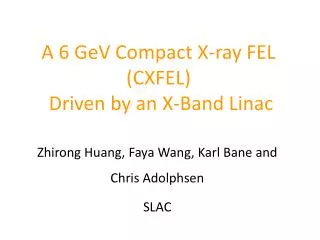
PPM Klystron Performance(75 MW, 1.6 ms, 120/150 Hz, 55% Efficiency Required) KEK/Toshiba Four tubes tested at 75 MW with 1.6 ms pulses at 50 Hz (modulator limited). Efficiency = 53-56%. SLAC Two tubes tested at 75 MW with 1.6 ms pulses at 120 Hz. Efficiency = 53-54%.
Reflected Power – Normal Pulse Transmitted 14 mm Power – Tear Event Time (100 ns / div) Klystron Tear Events • Character of events suggest they originate in output cavity – visual inspection inconclusive so far. • At 75 MW, iris surface field ~ 70 MV/m, lower than in 3% vg structures, but higher than sustainable (~ 50 MV/m) in waveguide with comparable vg (~ 20%) as the klystron TW output structures. • May require multi-beam klystron approach for stable > 50 MW, 1.6 ms operation. KEK PPM2 Output Structure
For RF Unit Test, Four 50 MW Solenoid-Focused Klystrons Installed in the Eight-Pack Modulator (In Place of Two 75 MW PPM Klystrons)
TE02 TE01 TE01 TE02 For NLC/GLC, Use Dual Moded Delay Line to Reduce Delay Line Length in Half
Also Use Over-Height Planar Waveguide to Lower Surface Fields Design for < 50 MV/m for 400 ns pulses Example: Power Splitter
Dual-Moded SLED-II Performance(475 MW, 400 ns Pulses Required) Output Power (Gain = 3.1, Goal = 3.25) Combined Klystron Power
NLC Accelerator Structure Requirements Convert rf energy to beam energy efficiently. Short-range transverse wakefields small to limit linac emittance growth: iris radius limited to 17% of rf wavelength (i.e. a/l = 17%). Long-range wakefields suppressed so bunch train effectively acts as a single bunch. Dipole mode power coupled out for use as guide for centering the beam in the structure. Operate reliably at the design gradient and pulse length. NLC/GLC Structures were developed by a FNAL/KEK/SLAC collaboration –CERN/KEK/SLAC now developing 11%-13% a/l structures that run at ~ 100 MV/m
High Gradient Structure Development • Since 1999: • Tested about 40 structures with over 30,000 hours of high power operation at NLCTA. • Improved structure preparation procedures - includes various heat treatments and avoidance of high rf surface currents. • Found lower input power structures to be more robust against rf breakdown induced damage. • Developed NLC-Ready ‘H60’ design with required wakefield suppression features. 50 cm ‘T53’ Structure
H60 Structure Cells and Coupler Assembly High Power Output Coupler Cells with Slots for Dipole Mode Damping Port for Extracting Dipole Mode Power
Dipole Mode Density Wakefield Damping and Detuning Ohmic Loss Only Frequency (GHz) Detuning Only Measurements Wakefield Amplitude (V/pC/m/mm) Time of Next Bunch Damping and Detuning Time After Bunch (ns)
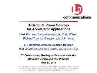
Breakdown Rate History (Goal < 0.1/hr) Four H60 Structures at 65 MV/m t = 600 hr t = 400 hr Breakdown Rate at 60 Hz (#/hr) with 400 ns Pulses t = 400 hr t = 400 hr Hours of Operation Hours of Operation
RF Unit Test in 2003-2004 Powered Eight H60 accelerator structures in NLCTA for 1500 hours at 65 MV/m with 400 ns long pulses at 60 Hz and accelerated beam From Eight-Pack From Station 2 3 dB From Station 1 3 dB 3 dB 3 dB 3 dB Beam
High Power (Multi-MW) X-Band Applications • Energy Linearizer • Single Structure: in use at LCLS, planned for BNL, PSI, Fermi/Trieste and SPARX/Fascati • Deflecting Cavity for Bunch Length Measurements • CERN Linear Collider Structure Development • 100’s of MeV to Many GeV Linacs • LLNL 250 MeV linac for gamma-ray production • SLAC 600 MeV energy ‘dither’ linacs for LCLS II • LANL 6-20 GeV linac for an XFEL source to probe proton-matter interactions • SPARX 1-2 GeV X-Band linac for their FEL • SLAC study of a 6 GeV Linac for a Compact XFEL (CXFEL) source • See my Thursday talk in WG4 for more details
CERN/CLIC X-band Test-Stand(Under Construction) Directional coupler Circular pumping port Klystron XL5 Mode convertors RF Valve High voltage modulator Circular waveguide F=50 mm SLED Pulse compressor CERN - CEA – PSI – SLAC
X-band Linac Driven Compact X-ray FEL Linac-1 250 MeV Linac-2 2.5 GeV Linac-3 6 GeV X BC1 BC2 X S Undulator L = 40 m X undulator rf gun LCLS-like injector L ~ 50 m 250 pC, gex,y 0.4 mm X-band main linac+BC2 G ~ 70 MV/m, L ~ 150 m • Use LCLS injector beam distribution and H60 structure (a/l=0.18) after BC1 • LiTrack simulates longitudinal dynamics with wake and obtains 3 kA “uniform” distribution • Similar results for T53 structure (a/l=0.13) with 200 pC charge
Operation Parameters * Allows ~ 50-70 ns multibunch operation
Layout of Linac RF Unit 50 MW XL4 400 kV 100 MW 1.5 us 12 m 480 MW 150 ns Nine T53 Structures (a/l = 13%) or Six H60 Structures (a/l = 18%)
NLC RF Component Costs (2232 RF Units) For the 6 GeV CXFEL, assume the cost per item will be 4 times higher. For 70 MV/m operation:
Gradient Optimization Assuming 1) Tunnel cost 25 k$/m, AC power + cooling power 2.5 $/Watt 2) Modulator efficiency 70%, Klystron efficiency 55%.
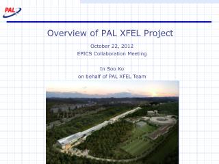
Structure Breakdown Rates with 150 ns Pulses At 70 MV/m, Expect Rate Less Than 0.01/hr at 120 Hz • H60VG3R scaled at 0.2/hr for 65 MV/m,400 ns, 60Hz • T53VG3R scaled at 1/hr for 70 MV/m, 480 ns, 60 Hz • Assuming BDR ~ G26, ~ PW6
Single Bunch Wake Tolerances • In both Linac-2 and Linac-3, short-range transverse wakefields in H60 are not a major issue in that: - An injection jitter equal to the beam size yields a 1% emittance growth in Linac-2 and .003% growth in Linac-3 - Random misalignments of 1 mm rms, assuming 50 structures in each linac, yields an emittance growth of 1% in Linac-2, 0.1% in Linac-3. • With the T53 structure, the jitter and misalignment tolerances are about three times smaller for the same emittance growth. • The wake effect is weak mainly because the bunches are very short.
X-Band Revival • The 15 year, ~ 100 M$ development of X-band technology for a linear collider produced a suite of robust, high power components. • With the low bunch charge being considered for future XFELs, X-band technology affords a low cost, compact means of generating multi-GeV, low emittance bunches. • Gradients of 70-100 MV/m possible vs ~ 25 MV/m at S-Band and ~ 35 MV/m at C-Band • The number of XFELs is likely to continue to grow (e.g., normal conducting linacs being considered in Korea and China). • To expand X-band use, need to have components industrialized and a small demonstration accelerator built, such as the 150 MeV C-band linac at Spring-8 in Japan where they have done light source studies.