Download
1 / 33
440 likes | 903 Views
Prospects of High Power Millimeter Wave Radar A. Tolkachev , B. Levitan JSC «Radio Physics», Moscow M. Petelin Institute of Applied Physics, Nizhny Novgorod. Advantage of MMW radar. HIGH PRECISION: favorable relation between antenna diameter and beamwidth

E N D
Prospects of High Power Millimeter Wave RadarA. Tolkachev , B. LevitanJSC «Radio Physics», MoscowM. PetelinInstitute of Applied Physics, Nizhny Novgorod
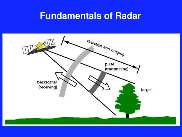
Advantage of MMW radar HIGH PRECISION: • favorable relation between antenna diameter and beamwidth • high range resolution, if relative bandwidth is fixed
Difficulties of MMW radar • wave absorption by atmosphere: 0.05 dB/km at Ka band, 0.4 dB/km at W band; • wave scattering by rain and snow. Dry high sites are preferable
Natural applications of MMW radar: • short distance radar, • cloud radar, • space surveillance radar (elevation angles over 20 degrees, detection range up to 2000 km) The last one needs the highest power.
MMW radar transmitters • Entirely solid-state phased arrays are capable to radiate only relatively low powers. • High powerscan be produced bytransmitters with final cascades based onvacuum tubes.
HEMISPHERIC COVERAGE RADAR COMPLEX: X-band “ARGUN” & Ka-band “RUZA”
34 GHz /1 MW semi-active phased array Elementary transmit-receive Cossegrain module
Velocity lag of plasma trace fromreentry vehicle measuredby «Ruza» radar γ [m2/kg]= 1/CB - ballistic coefficient К – airframes and motor cases;ГЧ – reentry vehicle; МЭО – metallized reference reflector; ЛЛЦ – light decoy; НЭО – inflatable reference reflector;ТЛЦ – heavy decoy Radar data and theoretical estimates obtained on the data reveal the possibility of discriminating the multiple ballistic target at the height none the less (target reentry elevation 30o , velocity 5 km/s) : Inflatable reference reflector – 125 km Light decoys – 90 – 110 km Airframes and motor cases – 75 km Theoretical and experimental discrimination height of observed target as a function of its ballistic coefficient Realization of plasma trace returns with regard to tracked reentry vehicle returns Oscillograms of the tracked reentry vehicles returns
Solid-state amplifier gyroTWT antenna diplexer diplexer diplexer diplexer diplexer diplexer gyrotwystrons HUSIR W-band transmitterwith synthesized frequency band
HUSIR is specified for up-to-geostationary satellite imaging with 3 cm range resolution.
HPMMW radar problems • high power amplifiers, • multiplexers, • duplexers, • monopulse configurations, • passive-active phased arrays, • signal processing.
MEDIUM POWER RADAR • mechanical hemispherical coverage, • agile electrically controlled wave beam forming and scanning.
phase front Controlled phase shifters Controlled time delays t 3 Agile high-range-resolution broad-angle scanning needs sub-arrays with controlled time delays
A project of mobile MMW radar
HIGH-POWER RADAR Wave combining Frequency band synthesizing Transmit-receive switching
SPACE DEBRIS SURVEILLANCE RADAR RCS 0.01 m2detection range 1500 km Angular precision 10”
Discrete wave beam scanner Possible applications: • DLDS of electron-positron collider, • suppression of plasma instabilities
2 N-1 SN-1 S2 N-2, N-1 , N 1, 2 , … N N 3 , … N S1 SN-2 1 N-2 Multiplexerfor radar with synthesized frequency band
Resonant diplexer Output 1 1 1 2 Resonant frequency Diplexer Non-resonant frequency Output 2 Output 2 Output 1 |2 - 1 |<< 1,2
Common TR control and signal processing unit 1 TR module Multiplexer 2 TR module N TR module jtransmit-receive module j Amplifier TR switch Analogous receiver Digitized signal ADC Synthesizing of frequency band
MULTIPLEXER THEORY • Diplexer transmission • Diplexer non-resonant loss • Transmit mode: output spectrum • Receive mode: signal in j-th channel
1 2 3 4 5 1 2 3 4 5 Transmit mode of multi-channel communication system Transmit mode of radar with synthesized frequency band
RADAR WITH SYNTHESIZED FREQUENCY BAND Target image obtained with optimized MTI algorithm
polarizer dummy load antenna receiver polarization separator receiver transmitter protector TRANSMIT-RECEIVE SWITCH antenna duplexer T R
DUPLEXERS TRANSMIT ANTENNA RECEIVE MONOPULSE “SUFFA”(the simplest version)
EIK GA n n 1 1 Trans-mitter Multi-plexer Multi-plexer 2 2 antenna duplexer Receiver Synthesized-frequency-band “SUFFA”
space debris detection RADAR